Gas concentration sensor

Inactive Publication Date: 2001-10-30
NGK SPARK PLUG CO LTD
View PDF6 Cites 35 Cited by
  • Summary
  • Abstract
  • Description
  • Claims
  • Application Information

AI Technical Summary

Benefits of technology

is to provide a gas concentration sensor capable of accurately measuring propagation time of a direct wave and capable of measuring the concentration of specific gas, such as purge gas, or the concentration of specific gas for use in a fuel ce

Problems solved by technology

Such an ultrasonic sensor has been developed, but a satisfactory ultrasonic sensor has not yet been developed.
This causes difficulty in detecting the modulation point of the direct wave, resulting in a failure to accurately measure the propagation time of the direct wave.
Accordingly, accurate control of purge gas concentration on the basis of a measured purge gas concentration becomes considerably difficult.
However, the disclosed sensor involves a certain degree of heating.
However, this sensor has a problem in that an electrode is poisoned by CO, which is generated in a large amount during start-up, and that humidity dependency is high.
However, when a gas component having a low molecular weight, such as hydrogen gas, is to be detected, the speed of sound becomes considerably high.
As a result, the indirect wave is highly likely to overlap the direct wave, causing difficulty in detecting a modulation point.
Therefore, measurement of propagation time becomes considerably difficult.
In the case of receiving such a high-speed sound wave, even a controller's switching noise, which is generated at the time of transmission of an ultrasonic wave, and reverberations overlap a received wave reflected from a reflection surface, thus disturbing wave reception.
There can also be a problem with an ultrasonic gas concentration sensor that, when the flow velocity of intake air is high, with a resultant disturbance of flow, an ultrasonic wave transmitted into the intake air suffers unstable amplitude attenuation, resulting in a failure to receive an ultrasonic w

Method used


Image

  • Gas concentration sensor
  • Gas concentration sensor
  • Gas concentration sensor

Examples


Example

First Embodiment

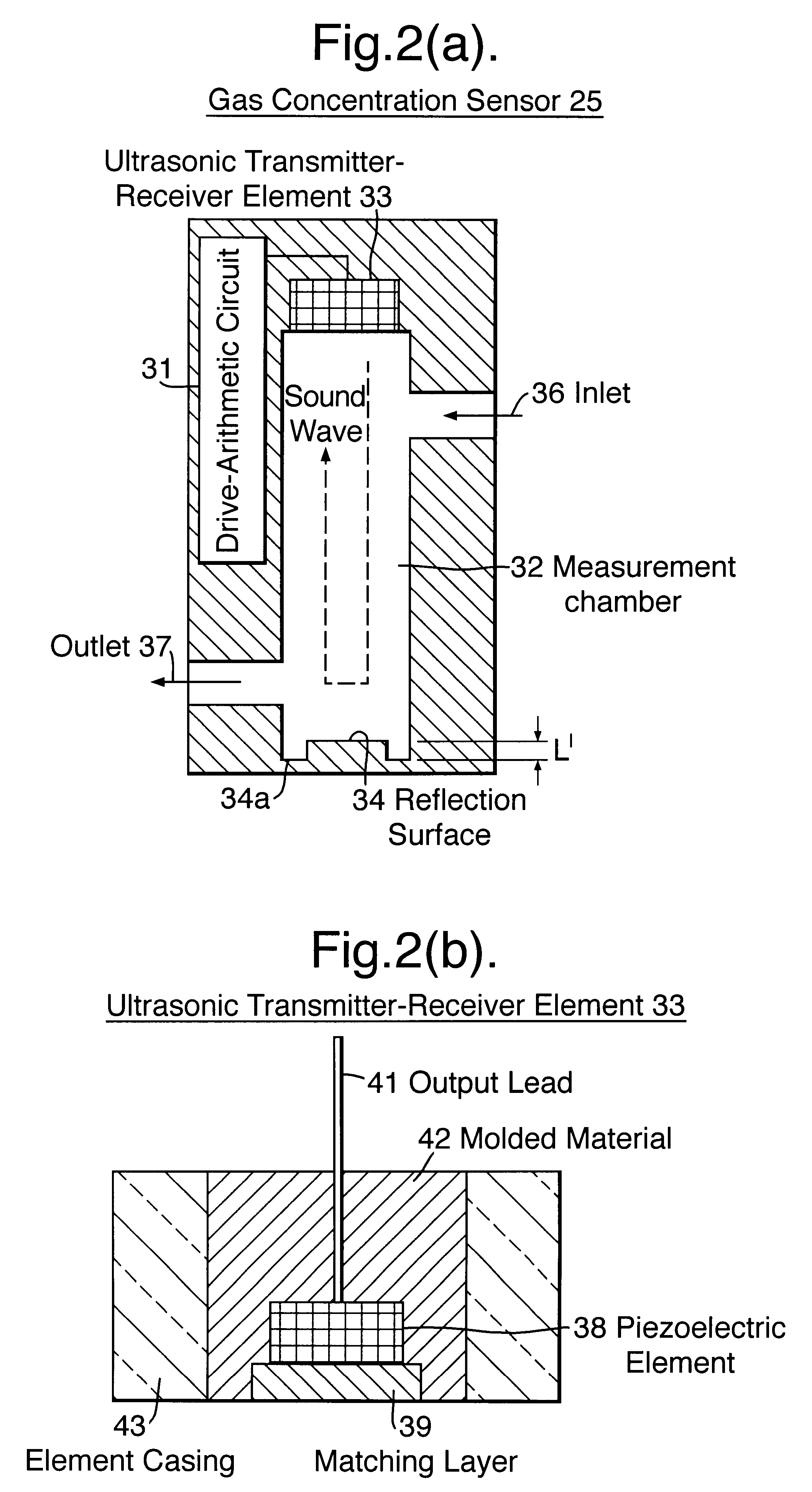
A gas concentration sensor according to the present embodiment utilizes an ultrasonic wave so as to measure vaporized fuel concentration.

First, the configuration of a system which employs a gas concentration sensor of the present embodiment will be described.

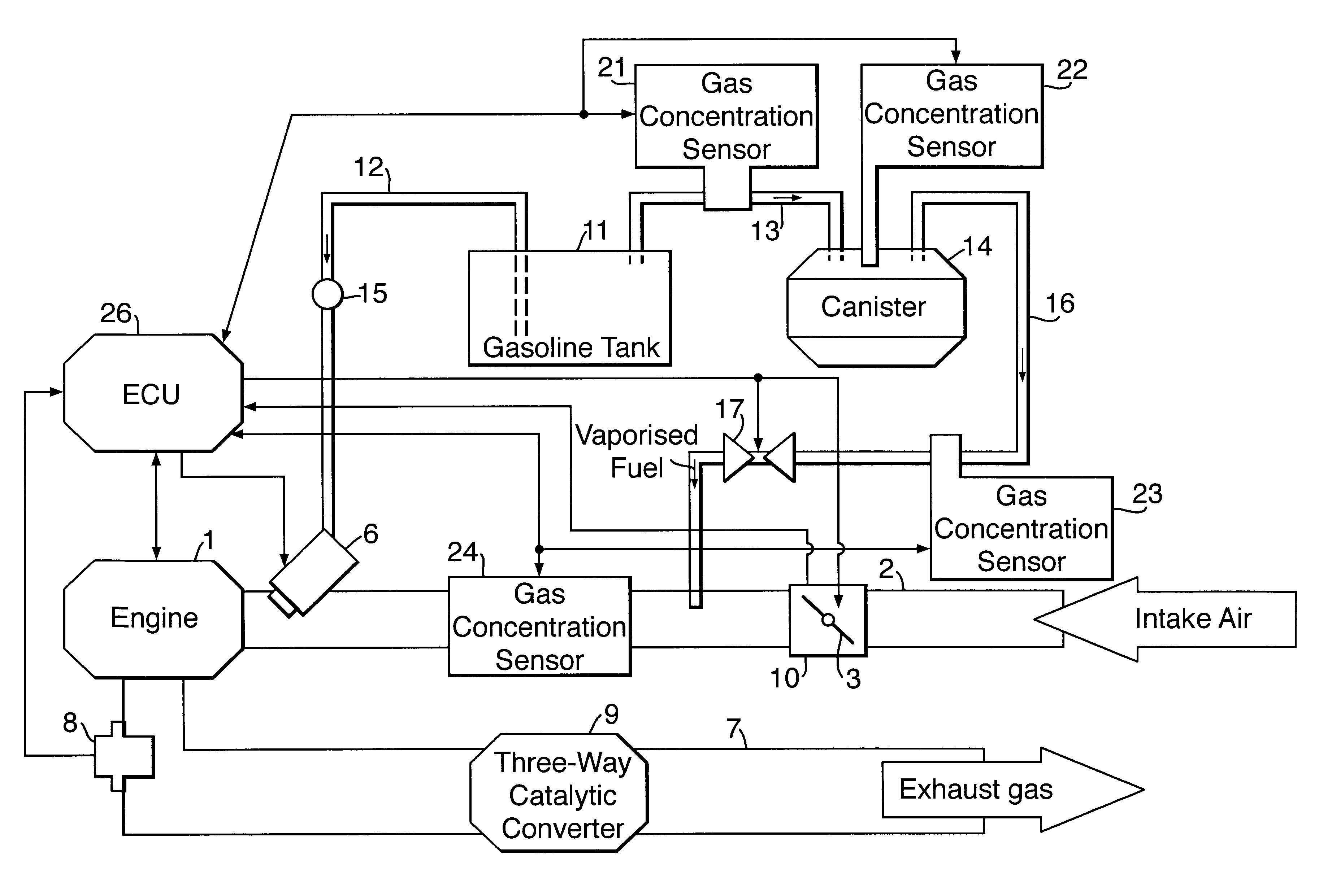
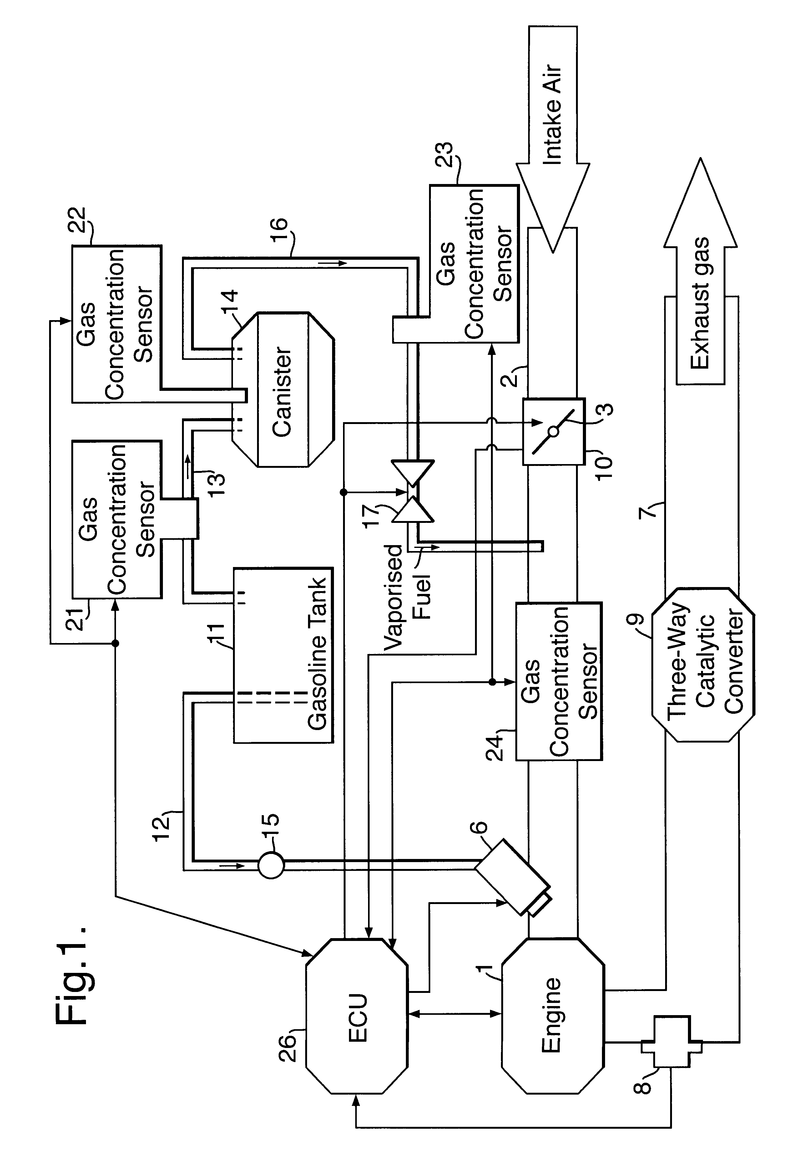
FIG. 1 is a diagram showing a system configuration including gas concentration sensors.

As shown in FIG. 1, a throttle valve 3 for regulating intake air volume, a fourth gas concentration sensor 24 for detecting purge gas concentration, and an injector 6 for injecting fuel, from upstream side to downstream side, are disposed on an intake pipe 2 of an engine 1.

An oxygen sensor (full-range-type air-fuel ratio sensor) 8 for detecting oxygen concentration in exhaust gas and a three-way catalytic converter 9 for purifying exhaust gas, from upstream side to downstream side, are disposed on an exhaust pipe 7 of the engine 1.

A path for supplying fuel to the engine 1 includes a first supply system for supplying liquid fuel...

Example

Second Embodiment

Next, a second embodiment will be described.

Description of features similar to those of the above-described first embodiment will be omitted or simplified.

As shown in FIG. 11(a), the present embodiment is characterized in that the area of the reflection surface 34 is greater than that of an opening surface of the ultrasonic element 33 (specifically, the area of a portion for transmitting / receiving an ultrasonic wave).

As shown in FIG. 11(b), in the case where the area of the reflection surface 34 is smaller than that of the opening surface of the ultrasonic element 33, ultrasonic-wave components transmitted in parallel with a direct wave propagating along a path 1 include an indirect wave which impinges on a side wall of the measurement chamber 32 in the vicinity of the reflection surface 34. The indirect wave includes a component which, after impinging on the side wall of the measurement chamber 32, propagates along the side wall to the reflection surface 34 and is ...

Example

Third Embodiment

Next, a third embodiment will be described.

Description of features similar to those of the above-described first embodiment will be omitted or simplified.

The present embodiment is intended to measure the concentration of a gas component having a low molecular weight, such as hydrogen gas, by means of an ultrasonic sensor; i.e., to effectively detect such a gas concentration even when the speed of sound becomes considerably high during measurement of gas concentration. Thus, the present embodiment is characterized by specifying a distance equivalent to the distance L between the reflection surface 34 and the outer surface of the ultrasonic element 33 (FIGS. 6 and 7) and a distance equivalent to the distance L' between the outer surface of the ultrasonic element 33 and the bottom surface of the depression 34a formed on the reflection surface 34.

First, the structure of a gas concentration sensor 325 employed in the present embodiment will be described.

The gas concentrat...


PUM


Abstract

A gas concentration sensor comprises an ultrasonic element 33 opposite a reflection surface 34. A depression 34a is formed on an edge portion of a reflection surface 34 which is in contact with a side wall of a measurement chamber 32 such that a bottom surface of the depression 34a is substantially in parallel with the reflection surface 34. The distance between the ultrasonic element 33 and the edge portion of the reflection surface 34 becomes greater than the distance between the ultrasonic element 33 and a central portion of the reflection surface 34. As a result, an indirect wave, which impinges obliquely on the side wall of the measurement chamber 32 and propagates along the side wall, is reflected from the bottom surface of the depression 34a and propagates. Thus, the propagation distance of this indirect wave becomes greater as compared to the case where the reflection surface 34 is flat, so that the indirect wave is not combined with a direct wave in the vicinity of a modulation point of the direct wave. That is, since the modulation point of the direct wave can be detected accurately, a time interval between a modulation point of a transmitted wave and that of a received wave can be measured as the propagation time of an ultrasonic wave, thereby enabling accurate determination of gas concentration.

Description

Field of the InventionThe present invention relates to a gas concentration sensor for measuring the concentration of combustible gas, such as vaporized fuel, contained in, for example, intake air to be supplied into an intake pipe of, for example, an internal combustion engine, or for measuring the concentration of a gas component in fuel gas of a fuel cell or in exhaust gas. 2. Description of the Related ArtConventionally, a fuel supply system for supply of fuel from a fuel tank to an engine includes a first supply system which functions in the following manner. Fuel is pumped from the fuel tank by means of a fuel pump and is then sent to an injector through a fuel pipe.The fuel supply system further includes a second supply system which functions in the following manner. Vaporized fuel generated within the fuel tank is temporarily adsorbed by a canister. Accumulated vaporized fuel is purged from the canister and is sent as purge gas to an intake pipe.Accordingly, in addition to fu...

Claims


Application Information

Patent Timeline
IPC IPC(8): G01N29/02G01N29/22G01N29/024
CPCG01N29/024G01N29/222G01N2291/0212G01N2291/0217G01N2291/0258G01N2291/02809G01N2291/02836G01N2291/045
Inventor ISHIKAWA, HIDEKISATO, YOSHIKUNIBANNO, KEIGOISHIDA, NOBORUOSHIMA, TAKAFUMI
Owner NGK SPARK PLUG CO LTD
Why Eureka
Try Eureka