

Earphone antenna and wrieless device including the same
- Summary
- Abstract
- Description
- Claims
- Application Information
AI Technical Summary
Benefits of technology
Problems solved by technology
Method used
Image

Examples
Embodiment Construction
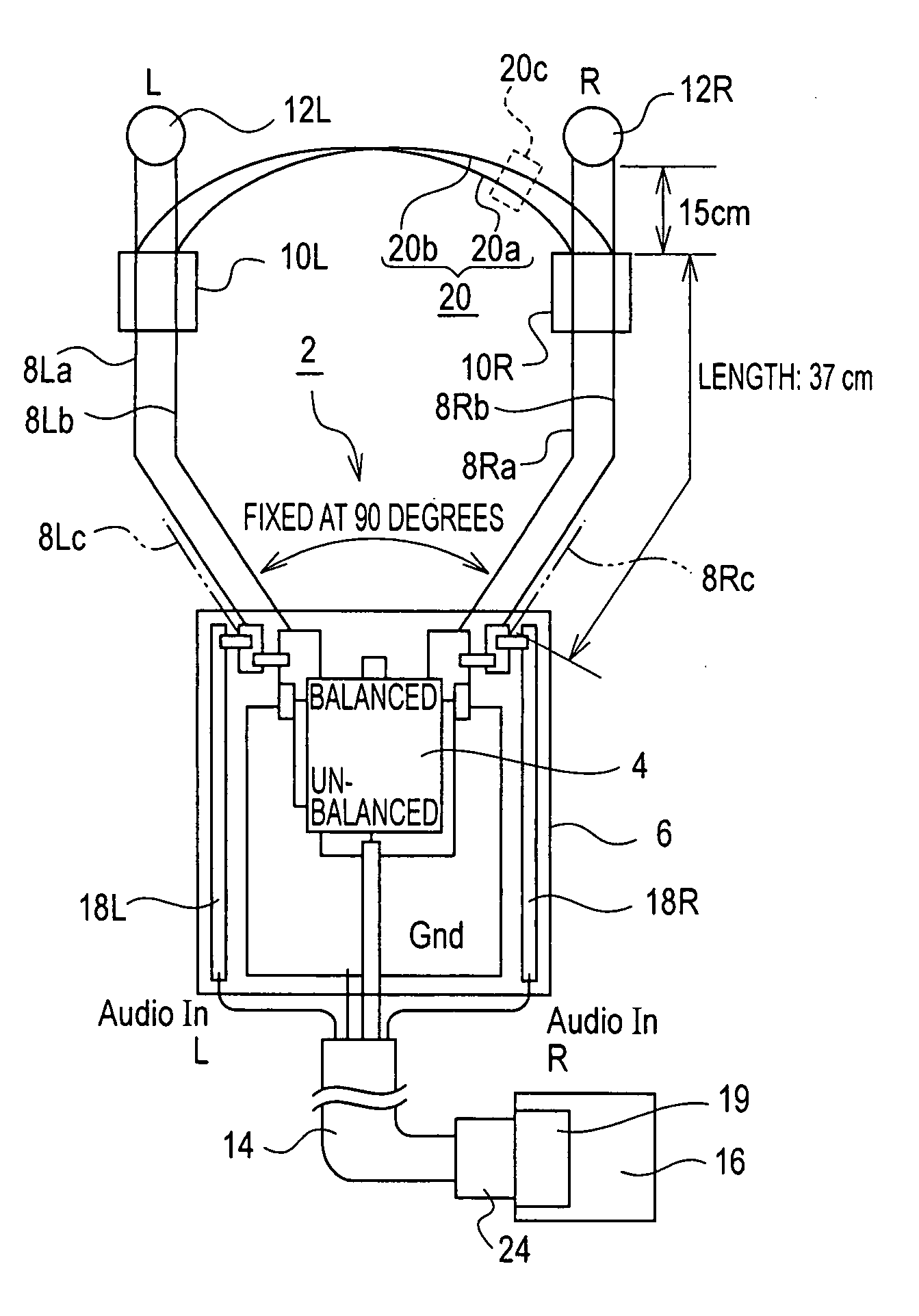
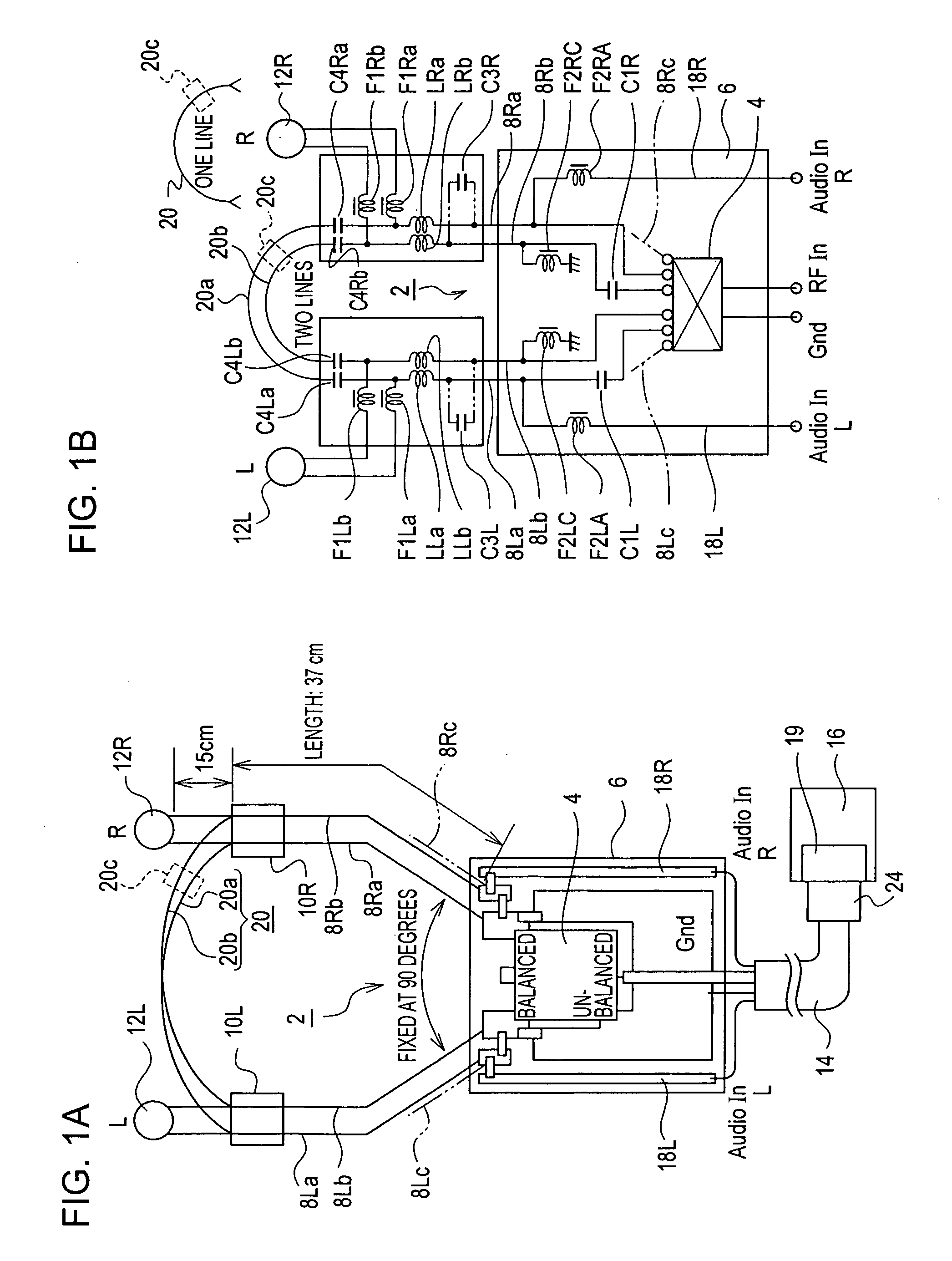
[0033] In an earphone antenna according to the present invention, basically, one end of a pair of audio / high-frequency signal lines is connected to one terminal of a balun at a balanced mode side, and the other end of the pair of audio / high-frequency signal lines is connected to the other terminal of the balun at a balanced mode side. A part of the pair of audio / high-frequency signal lines is connected to a left earphone unit, and another part of the pair of audio / high-frequency signal lines is connected to a right earphone unit. For a high-frequency signal, the pair of audio / high-frequency signal lines functions as a reception loop antenna. For an audio signal, portions of the pair of audio / high-frequency signal lines starting from the balun to connection points with the left and right earphone units function as audio signal transmission means for the left and right earphone units.
[0034] When, for example, the earphone antenna is used for a terrestrial digital broadcasting receive...
PUM
 Abstract
Description
Claims
Application Information