Wide bandwidth light source

a wide-bandwidth, light-emitting technology, applied in the direction of laser details, active medium materials, active medium shape and construction, etc., can solve the problems of side-band instability, limited wide-band light-emitting capacity, and modulation instability, and achieve excellent wide-band characteristics

Inactive Publication Date: 2005-09-15
SANTEC
View PDF3 Cites 36 Cited by
  • Summary
  • Abstract
  • Description
  • Claims
  • Application Information

AI Technical Summary

Benefits of technology

[0038] As described above, according to the present invention, transition an instable work of the wide bandwidth light source using the noise-like laser is inhibited by a simple configuration through monitoring the optical pulse, which is outputted by the optical pulse-generating means, or the white light, which is outputted by the white light-emitting means, to feedback to the optical pulse-generating means in order to realize the stable work the wide bandwidth light source. Hence, the present light source can be used as light source in various application fields by applying its excellent wide bandwidth characteristic.

Problems solved by technology

(1) The case of the wide bandwidth light source using active ions of rare earths arises a problem in that the bandwidth of the wide bandwidth light source is limited to a gain spectrum bandwidth of the active ions.
(2) The case of the wide bandwidth light source using the optical soliton pulse arises a problem in that (a) modulation instability is present (side-band instability.)
In addition, there is the problem of (b) nonlinearity / dispersion control is difficult.
However, there arises the following problem in this way: stable manufacture is difficultly realized and, also, reproducibility becomes difficult.
Therefore, when vibration and a temperature change occur in outside of the wide bandwidth light source, a signal spectrum and an output light amount vary sensitively and, thus, mode-locking is not stably reproduced.
Hence, in the worst case, mode-locking is not maintained.
From these causes, there is a problem in that mode-locking is difficult to operate in the wide bandwidth light source according to the present proposal.

Method used


Image

  • Wide bandwidth light source
  • Wide bandwidth light source
  • Wide bandwidth light source

Examples


example 1

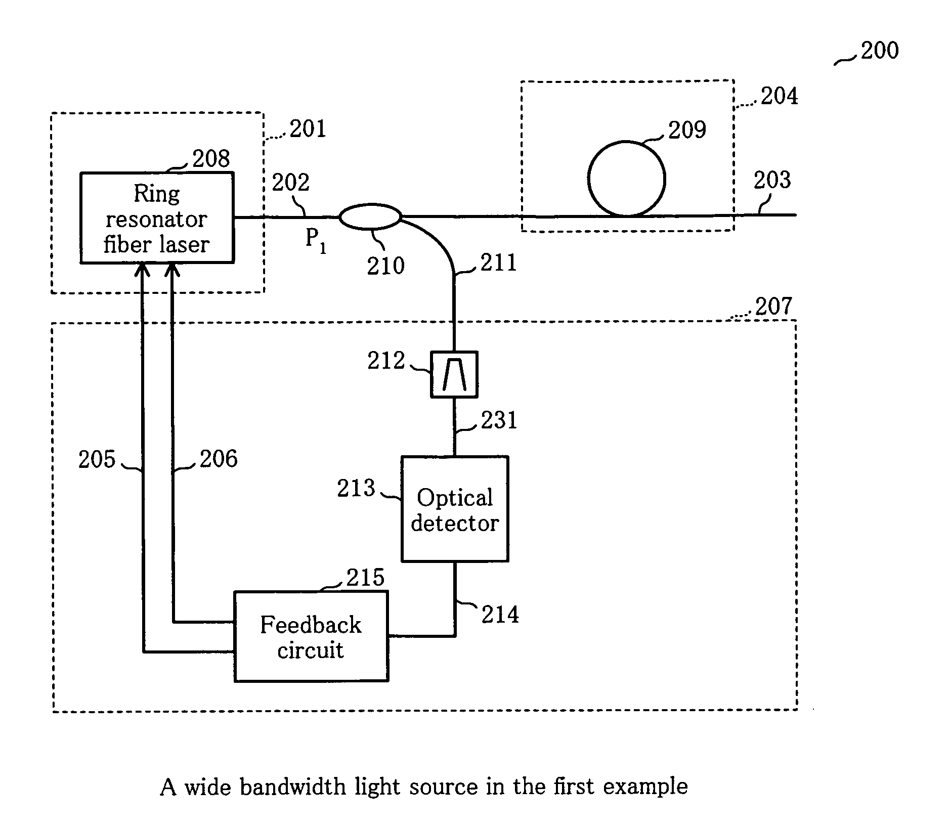
[0072]FIG. 6 shows the wide bandwidth light source according to the 1st example of the present invention. This wide bandwidth light source 200 is constituted by optical pulse-generating device 201, white light-emitting device 204 for emitting white light 203 by inputting optical pulse 202 outputted by optical pulse-generating device 201, and operation-stabilizing circuit 207 for controlling optical pulse-generating device 201 by producing the first and second feedback signals 205 and 206 by inputting optical pulse 202. Where, optical pulse-generating device 201 has ring resonator fiber laser 208. White light-emitting device 204 is constituted by HNL (highly nonlinear) fiber 209. In operation-stabilizing circuit 207 is inputted partially optical pulse 202 by optical coupler 210 as the splitting device. Optical pulse 211, which has been split, for monitoring is inputted into optical band pass filter 212 in operation-stabilizing circuit 207. Through optical band pass filter 212, a spec...

first modified example

OF THE FIRST EXAMPLE

[0084] In the first example as described above, the used optical band pass filter 212 was that in which central wavelength λ1 of passing optical pulse 211 for monitoring was 1450 nm and the full width half maximum was 1 nm. The present invention is not restricted to this example. In the next described first modified example, the central wavelength of optical band pass filter 212 (FIG. 6) is changed to 1540 nm.

[0085]FIG. 12 shows a spectrum change of the optical pulse as the noise-like laser, when the output of an pump light emitted from an pump laser diode as an pump light source is changed in this first modified example. Where, pump light 117 of wavelength from laser diode 116 shown in FIG. 7 is stepwise changed from 550 mW to the maximum 840 mW in a plurality of steps to express the relation between optical signal strength P1 and the wavelength of optical pulse 202 outputted from output optical fiber 129.

[0086]FIG. 13 shows the relation between power P of the...

second modified example

OF THE FIRST EXAMPLE

[0088]FIG. 14 corresponding to FIG. 7 shows modifiability of the optical pulse-generating device. The same reference numerals are attached to the same parts in FIG. 14 as those of FIG. 7 and, thus, description of these parts are omitted properly. In optical pulse-generating device 201A of this second modified example, small piezoelectric vibrator 241 is mounted on second single mode optical fiber 114. Driving power source 242 for piezoelectric vibrator 241 is worked by using a switch not illustrated. Then, piezoelectric vibrator 241 vibrates second single mode optical fiber 114 to make mode-locking. As piezoelectric vibrator 241, NB-59S, a product of TDK K.K., and a small buzzer, for example, can be used.

[0089] Not only in the wide bandwidth light source as described for the present example, but also, as a general rule, in this kind of the wide bandwidth light source, when it is subjected to a large disturbance and a large acceleration, mode-locking is not maint...


PUM

PropertyMeasurementUnit
wavelengthsaaaaaaaaaa

Abstract

PROBLEM TO BE SOLVED: to realize a wide bandwidth light source capable of a stable operation providing a less spectrum variation.
SOLUTION: Optical pulses 202 outputted by this optical pulse-generating device 201 are split by optical coupler 210. The one of split optical pulses is inputted in white light-emitting device 204 to emit the white light having the wide bandwidth. The other split is inputted in optical band pass filter 212 in operation-stabilizing circuit 207. Optical detector 213 detects a signal level of a specific wavelength and input in feedback circuit 215 to generate first and second feedback signals 205 and 206. Ring resonator fiber laser 208 uses any one of them and controls a rotation angle of the waveplate to realize stabilization of the output.

Description

FIELD OF THE INVENTION [0001] The present invention relates, that is exemplified by optical diagnosis employed in medical treatment and evaluation of a tomographic imaging apparatus or an optical communication component using optical interference, to a wide bandwidth light source necessary for fields particularly requiring the wide bandwidth light source and an operation method for such the wide bandwidth light source. BACKGROUND OF THE INVENTION [0002] One of fields expected for application of a wide bandwidth light source is clinical medicine. Conventionally, for finding early diseases such as a cancer, it has been widely carried out to obtain a tomographic image of a specific site of a human body by using a variety of approaches such as X-ray, sonic wave, or MRI (Magnetic Resonance Imaging tomography.) Such the tomographic image with higher resolution makes higher or more reliable pathologic diagnosis possible. Thus, as exemplified by OCT (Optical Coherence Tomography,) developme...

Claims


Application Information

Patent Timeline
Patent Type & Authority Applications(United States)
IPC IPC(8): H01S3/098H01S3/00H01S3/06H01S3/067H01S3/08H01S3/083H01S3/0941H01S3/10H01S3/106H01S3/13H01S3/136H01S3/16
CPCH01S3/06791H01S3/005H01S3/08H01S3/09415H01S3/106H01S3/1109H01S3/1112H01S3/1305H01S3/1608H01S2301/08
Inventor UEHARA, NOBORUTAKUSHIMA, YUICHIYASUNAKA, KENTARO
Owner SANTEC
Why Eureka
Try Eureka