Method of forming a stator assembly for rotary machine

Inactive Publication Date: 2001-03-20
UNITED TECH CORP
View PDF3 Cites 30 Cited by
  • Summary
  • Abstract
  • Description
  • Claims
  • Application Information

AI Technical Summary

Benefits of technology

A primary advantage of the present invention is the finished contour of the seal member, which results from avoiding disassembly of the vane clusters after machining and re-assembly of the vane clusters after cleaning. Another advantage is the cost of forming the modular section of the engine which results from blocking particles from entering the vane clusters during the machining operation and avoiding the work of assembly and disassembly to clean the stator clusters after machining. Still another advantage is the integrity of the seals between

Problems solved by technology

Plugging the holes will block the flow of cooling air and will cause premature failure of the turbine vane.
This results in a loss of engine efficiency and expense in replacing the turbine vane.
There may be difficulty in inserting the feather seal at final assembly in the appropriate slots be

Method used


Image

  • Method of forming a stator assembly for rotary machine
  • Method of forming a stator assembly for rotary machine
  • Method of forming a stator assembly for rotary machine

Examples


Embodiment Construction

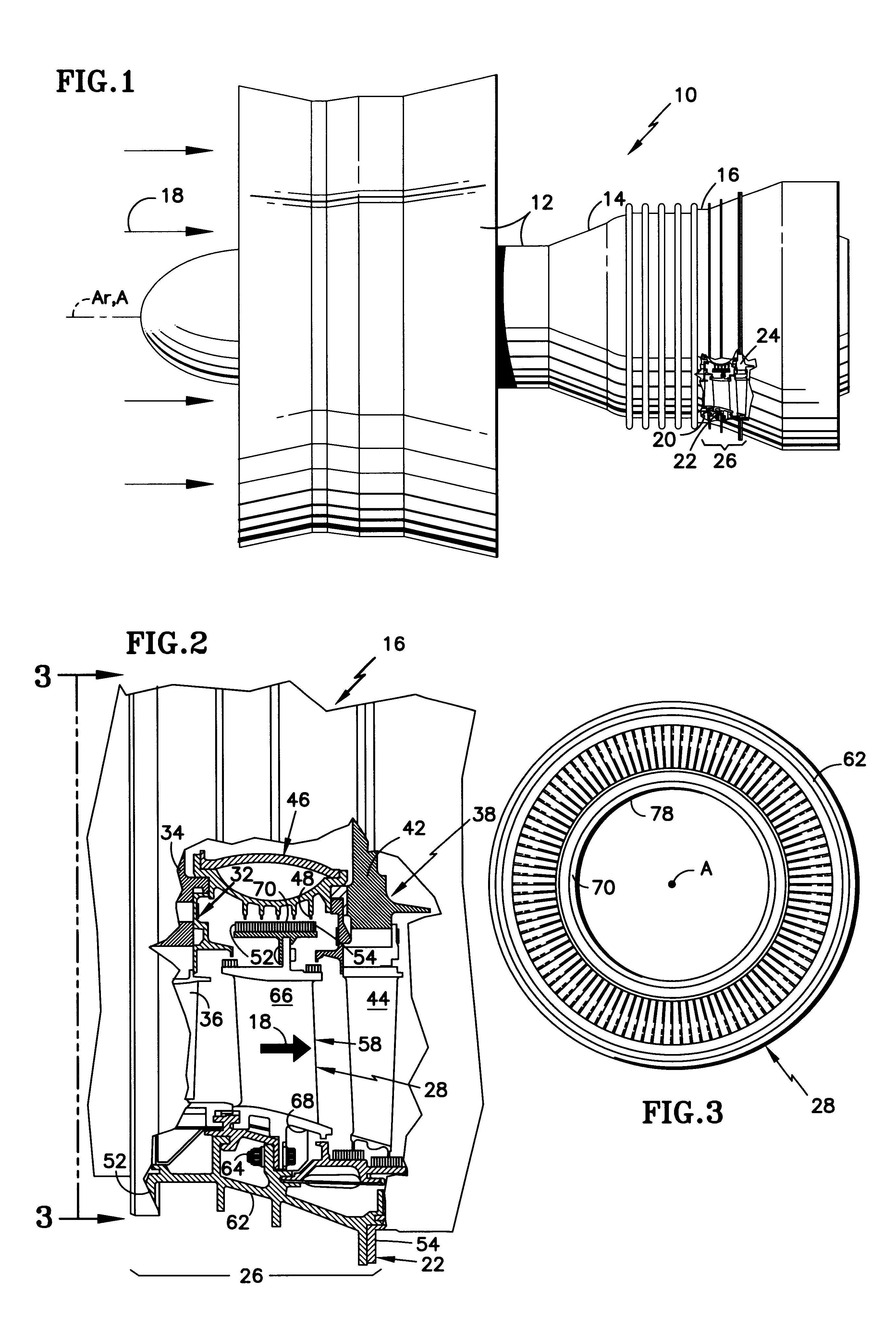
FIG. 1 is a side elevation view of a rotary machine 10, such as a turbofan gas turbine engine having an axis of rotation A.sub.r. The engine includes a compression section 12, a combustion section 14, and a turbine section 16. An annular, primary flowpath 18 for working medium gases extends axially through the sections of the engine. A by-pass flowpath 20 is outward of the primary flow path. The engine is partially broken away to show part of a stator 22 and a rotor 24 in the turbine section. The stator and rotor each include part of a modular unit 26 of the engine. The modular unit of the engine is disposed about an axis A which is at, or in close proximity to, the axis of rotation A.sub.r of the engine.

FIG. 2 is an enlarged side elevation view of the turbine section 16 of FIG. 1 showing a partial cross-sectional view of the modular unit 26. The stator 22 in the modular unit includes a stator assembly 28. The rotor includes two rotor assemblies 32,38. The first rotor assembly 32 ha...


PUM

PropertyMeasurementUnit
Flow rateaaaaaaaaaa
Flexibilityaaaaaaaaaa

Abstract

A method for forming a stator assembly 28 of a rotary machine 10 which includes masking the stator assembly during a machining operation on a seal member 70 is disclosed. Various detailed steps of the method are disclosed which decrease the cost of the method. In one embodiment of the method, the method includes disposing a shield assembly 98 about the stator assembly 28 to such an extent that individual members of the stator assembly need not be disassembled for cleaning.

Description

DESCRIPTION1. Technical FieldThis invention relates to a method for forming a modular section of a rotary machine and more particularly to a method that avoids the need to disassemble and reassemble portions of the stator assembly after a machining operation.2. Background of the InventionAn axial flow rotary machine, such as a gas turbine engine for an aircraft, has a compression section, a combustion section, and a turbine section. An annular flow path for working medium gases extends axially through the sections of the engine.The engine adds fuel to the working medium gases and burns the fuel in the combustion section to form hot, pressurized gases. The hot, working medium gases are expanded through the turbine section to extract energy as work from the gases. The energy is transferred to the compression section to raise the pressure of the incoming gases.The turbine section includes a rotor for receiving this work from the hot working medium gases. The rotor extends axially throu...

Claims


Application Information

Patent Timeline
IPC IPC(8): B23P6/00F01D25/28
CPCB23P6/002F01D25/285Y10T29/4932Y10T29/49318
Inventor DESCOTEAUX, SAMUEL S.
Owner UNITED TECH CORP
Why Eureka
Try Eureka