Electric power tool

a technology of electric power tools and power shafts, applied in the field of electric power tools, can solve the problems of change in the number of revolutions of the output shaft, and achieve the effects of avoiding a complicated housing structure, low torque range, and low torque rang

Inactive Publication Date: 2006-05-30
RYOBI
View PDF21 Cites 31 Cited by
  • Summary
  • Abstract
  • Description
  • Claims
  • Application Information

AI Technical Summary

Benefits of technology

[0011]According to the present invention, the trigger-limitation device determines the maximum stroke of the trigger to control the operation of the electric power unit, and the switching device, which is provided in a different place from the trigger-limitation device, operates the trigger-limitation device to move between the limited position and the unlimited position. As a result, an operator's fingers do not come into contact with the trigger-limitation device, when pulling the trigger. It is therefore possible to prevent the operator from working under a load, especially in case where a long period of working time is required, and avoid uncomfortable feeling of the operator. There is no possibility that the trigger-limitation device may be switched into the different mode, resulting in change in number of revolutions of the output shaft. Major modification made to the switch box is not required, so that general-purpose switch boxes can be utilized, thus providing advantageous effects.
[0012]In the other aspect of the present invention, the electric power tool may further comprises a flexible power transmission member through which the trigger-limitation device and the switching device are connected; and the housing may be composed of a pair of half portions having abutting edges, which are to be brought into contact with each other, the abutting edges defining a guide passage in which the flexible power transmission member is to be received.
[0013]According to the present invention, the trigger-limitation device and the switching device are connected through the flexible power transmission member, which is received in the guide passage formed on the abutting edges of the half portions of the housing. Consequently, the flexible power transmission member can be elastically deformed into any shape so as to enable the trigger-limitation device to be placed in any posture in a desired position. Receiving the flexible power transmission member in the guide passage formed on the abutting edges of the half portions of the housing makes it unnecessary to provide a specific space for receiving the power transmission member, thus avoiding a complicated structure of the housing.
[0014]In the other aspect of the present invention, the trigger-limitation device that is kept in the limited position may enable the trigger to be slid within a low torque range in the stroke thereof, the low torque range being provided at an upper section thereof with a constant torque zone.
[0015]According to the present invention, the low torque range is provided at an upper section thereof with the constant torque zone. As a result, even if there are variations in an amount of pulling operation of the trigger due to manufacturing error in a state that the trigger-limitation device is kept in the limited position, the output based on the stroke of the trigger is kept within the constant torque zone, which is provided in the upper section of the low torque range, thus preventing occurrence of variations in output properties in the low torque range and providing a stable low torque.
[0016]In the other aspect of the present invention, the switching device may be a lever, the flexible power transmission member may be formed of a substantially non-extensible material and the flexible power transmission member may be a wire.

Problems solved by technology

There is no possibility that the trigger-limitation device may be switched into the different mode, resulting in change in number of revolutions of the output shaft.

Method used


Image

  • Electric power tool
  • Electric power tool
  • Electric power tool

Examples


Embodiment Construction

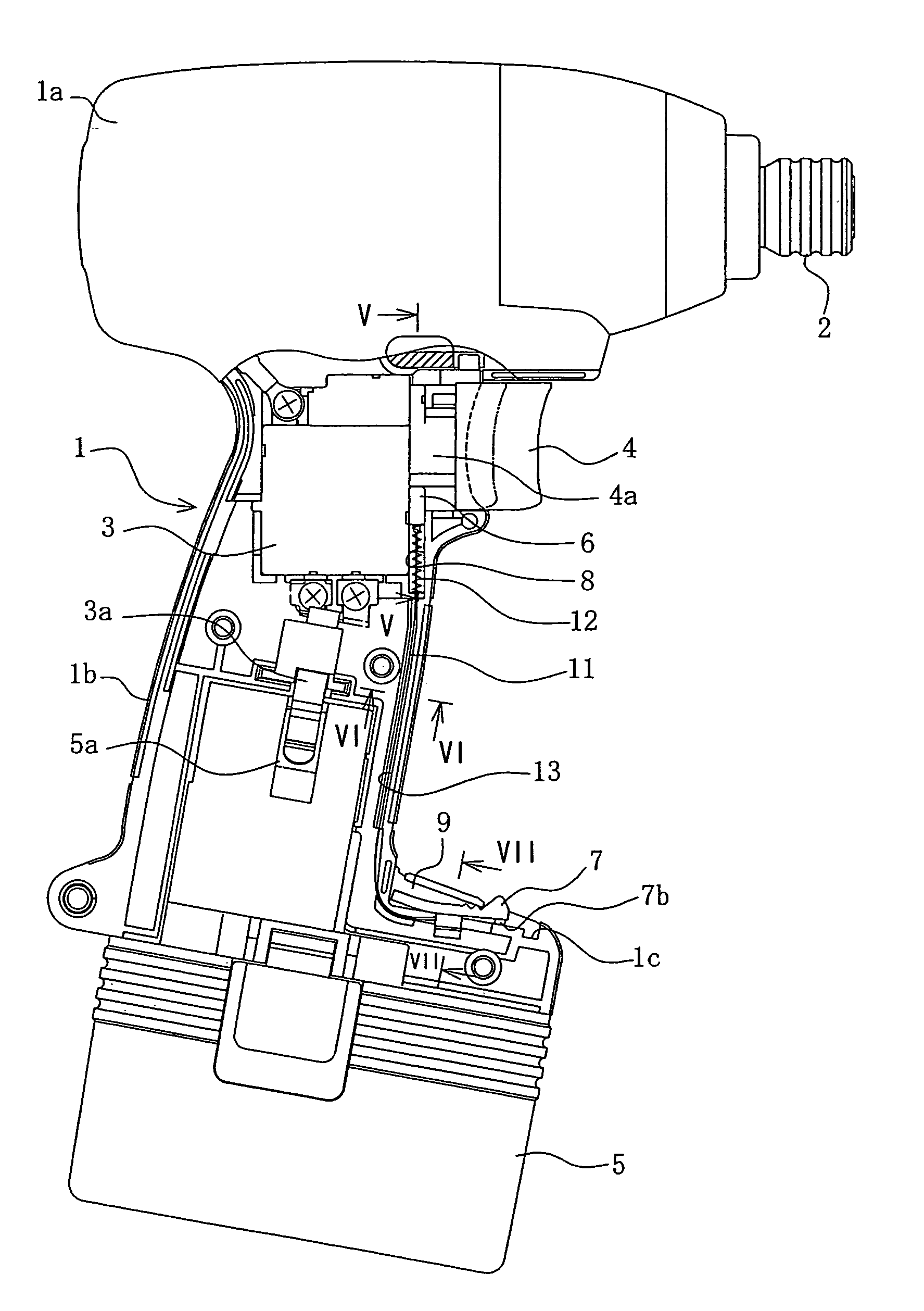
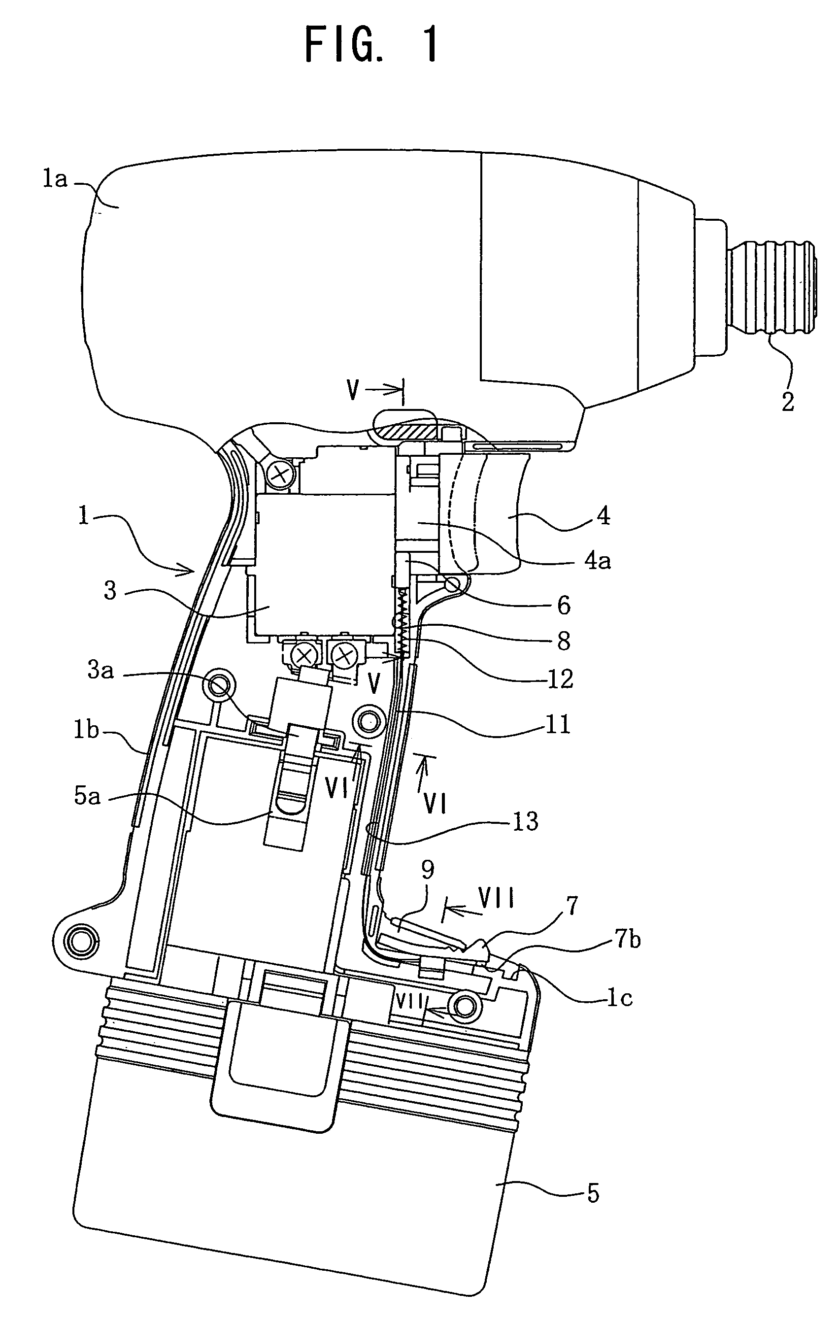
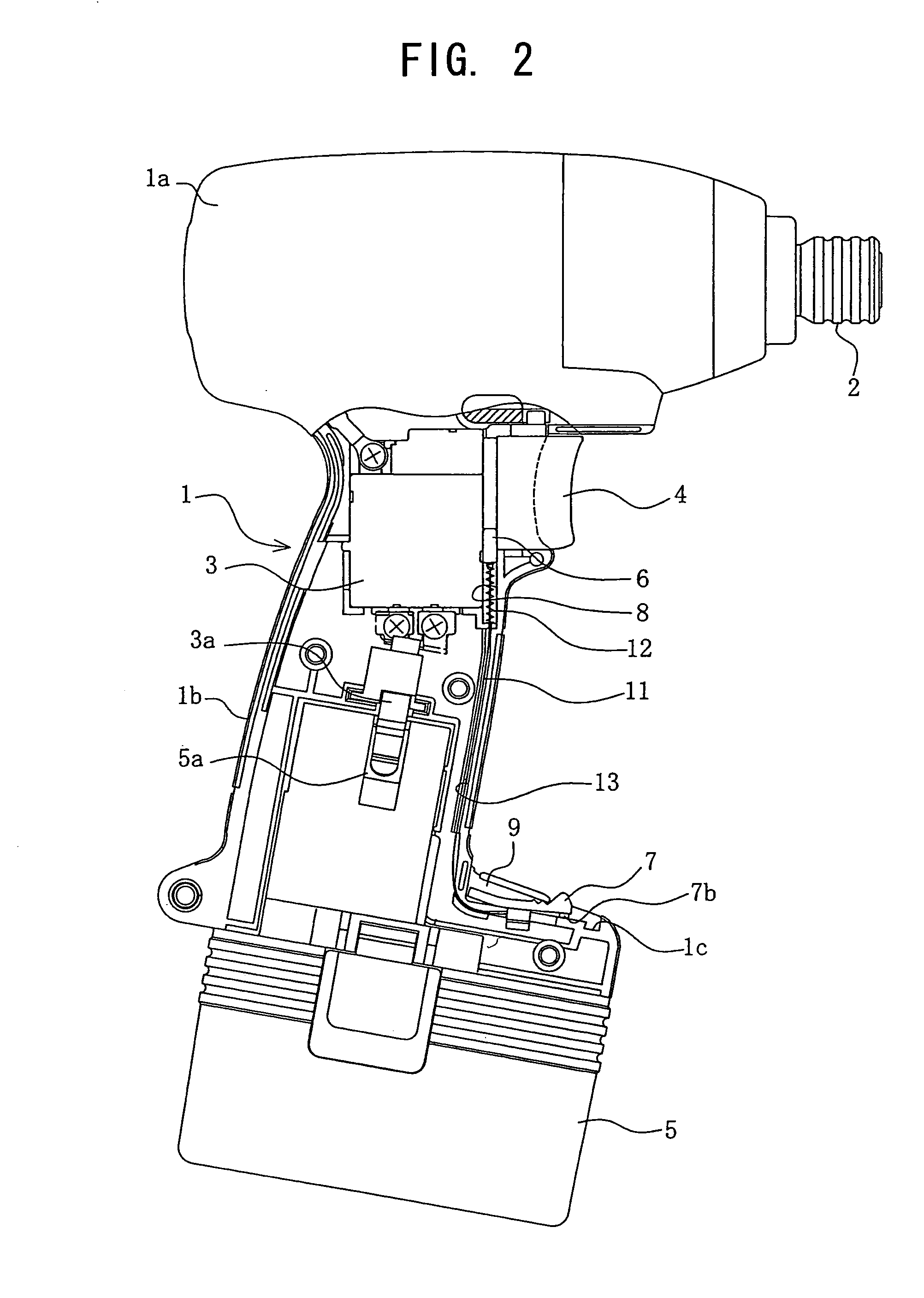
[0030]Now, embodiments of an electric power tool of the present invention will be described in detail below with reference to the accompanying drawings.

[0031]As shown in FIGS. 1 to 4, the electric power tool of the present invention is constructed as an impact driver. The impact driver has a fundamental structure including a housing 1, an electric power unit (not shown), a trigger 4, a trigger-limitation device 6 and a switching device 7.

[0032]More specifically, the impact driver has a housing 1, which is composed of a pair of half portions. The half portions of the housing 1 have abutting edges, respectively, which are to be brought into contact with each other on a plane that is in parallel with a drawing sheet. Such half portions are assembled into the housing 1 so that the abutting edges come into contact with each other on the above-mentioned plane. The half portions of the housing 1 are provided on their abutting edges at the front side of the housing 1 with grooves. Assemblin...


PUM


Abstract

An electric power tool includes a housing, an electric power, a trigger, a trigger-limitation device and a switching device. The housing receives the electric power unit having an output shaft. The trigger is slidably mounted on the housing so as to control operation of the electric power unit. The trigger-limitation device is mounted on the housing so as to be movable between a limited position and an unlimited position. The trigger-limitation device comes into contact with the trigger to limit a stroke of the trigger, when being kept in the limited position, and not coming into contact with the trigger to impose no limitation to the stroke of the trigger, when being kept in the unlimited position. The switching device is provided on the housing in a different place from the trigger-limitation device. The switching device operates the trigger-limitation device to move between the limited position and the unlimited position.

Description

BACKGROUND OF THE INVENTION[0001]1. Field of the Invention[0002]The present invention relates to an electric power tool having an output control structure.[0003]2. Related Art[0004]An electric power tool such as an impact driver has a switching structure, which enables the tool to be operated in the alternative of two modes in output in accordance with material to be worked and a finishing operation applied thereto, in order to prevent a head of a screw to be wrenched away from it shank or a screw to be turned excessively tightly, as shown in Japanese Patent Provisional Publication No. H7-326249.[0005]More specifically, such a kind of electric power tool has a trigger, which is connected to a switch box so that output increases in proportion to an amount of pulling operation of the trigger, and a dial type-adjustment knob is normally placed between the trigger and the switch box so that turning the knob between two positions enables the tool to be operated in the alternative of two ...

Claims


Application Information

Patent Timeline
Patent Type & Authority Patents(United States)
IPC IPC(8): H01H13/02B25B21/00B25F5/00B25F5/02H01H9/06
CPCH01H9/061H01H2009/065
Inventor YUASA, YUICHIWADA, YASUOMORIMUNE, SHINJI
Owner RYOBI
Why Eureka
Try Eureka