Conveyorized storage and transportation system

a technology of conveying storage and transportation system, which is applied in the direction of charge manipulation, furniture, instruments, etc., can solve the problems of not being able to execute parallel workpiece manipulations by stocker robots, unable to accept the conveying method of transportation in these industries, and unable to achieve single workpiece manipulation limitations, etc., to achieve convenient configuration

Inactive Publication Date: 2005-06-23
MIDDLESEX GEN INDS MESNE
View PDF14 Cites 32 Cited by
  • Summary
  • Abstract
  • Description
  • Claims
  • Application Information

AI Technical Summary

Benefits of technology

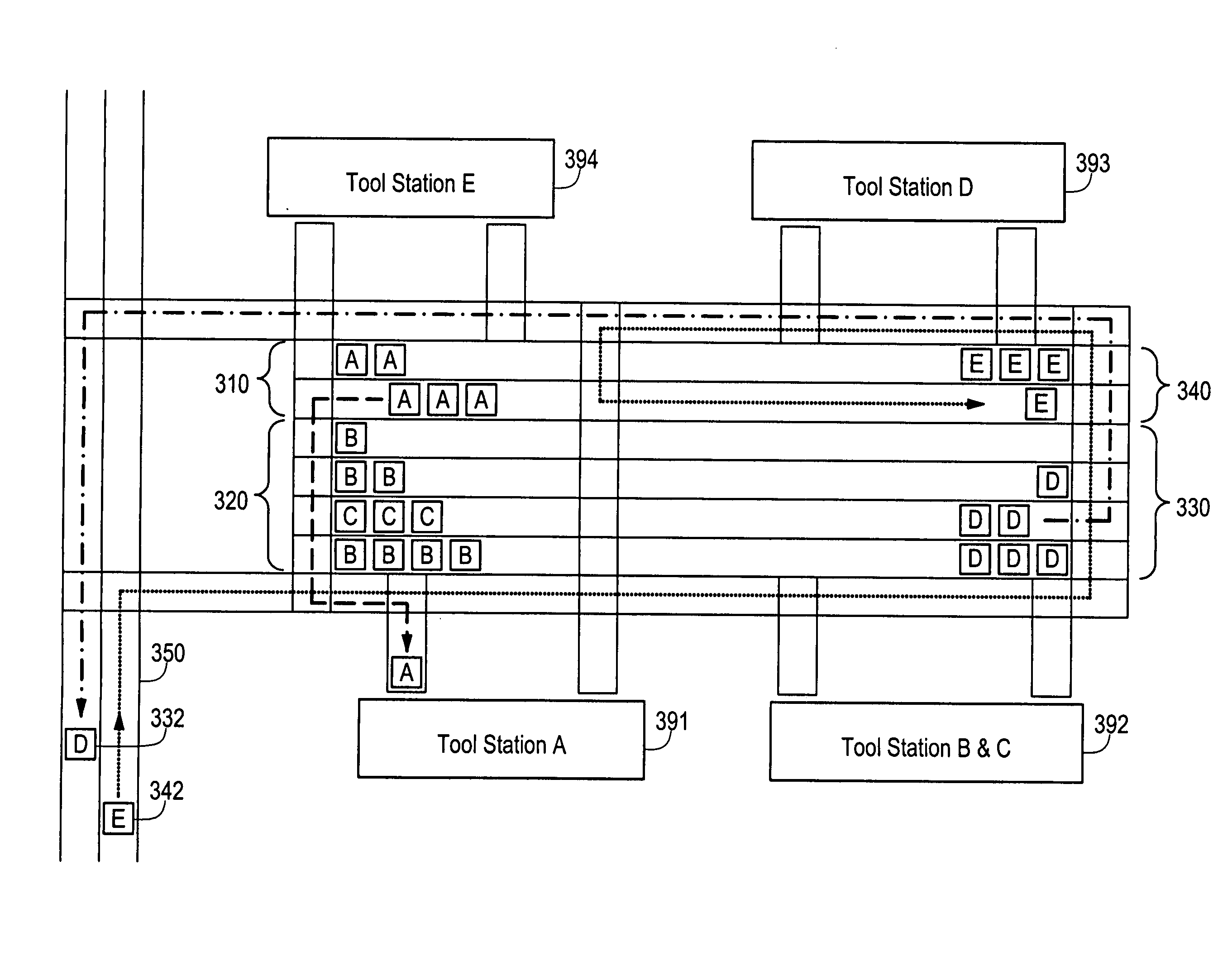
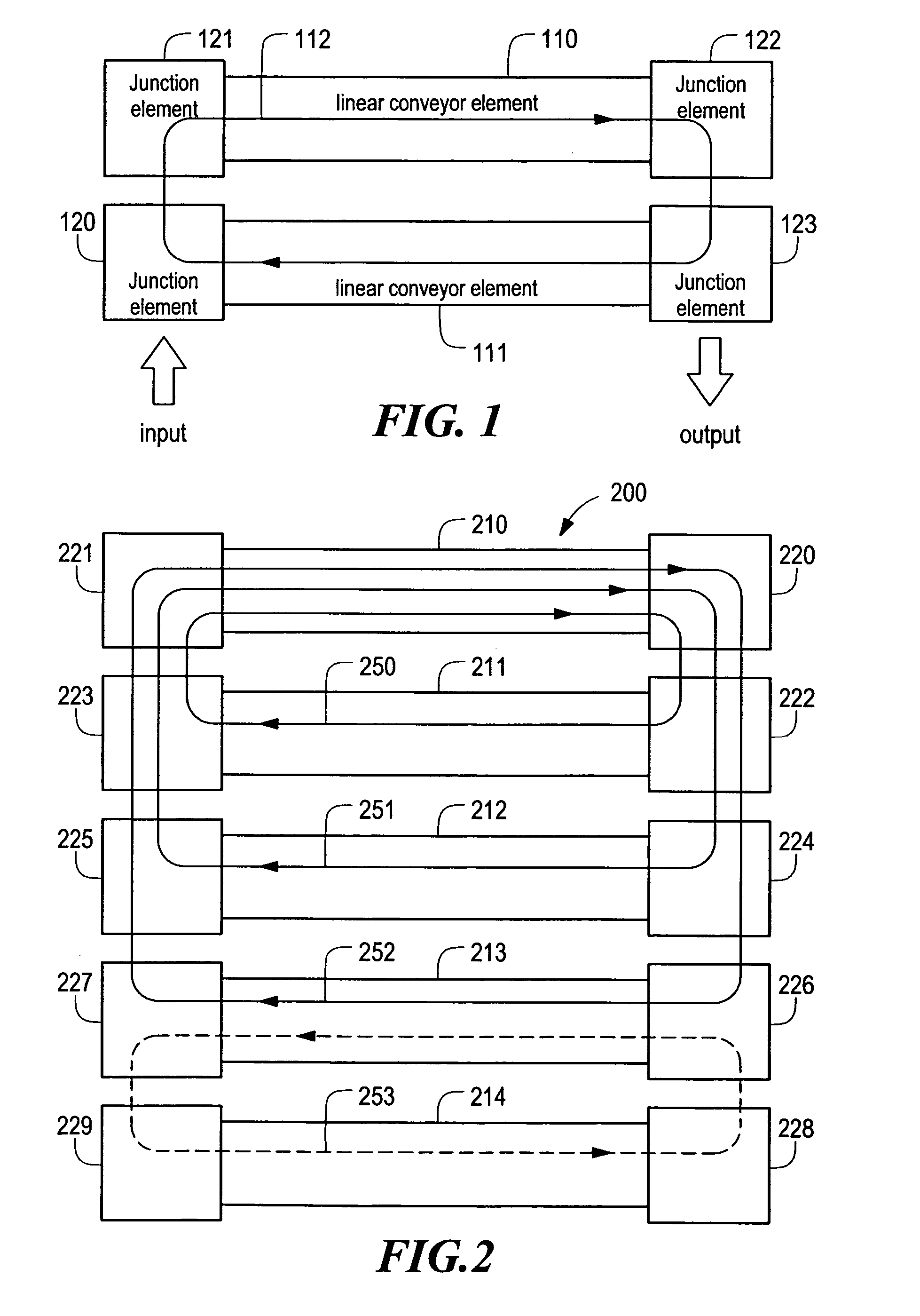
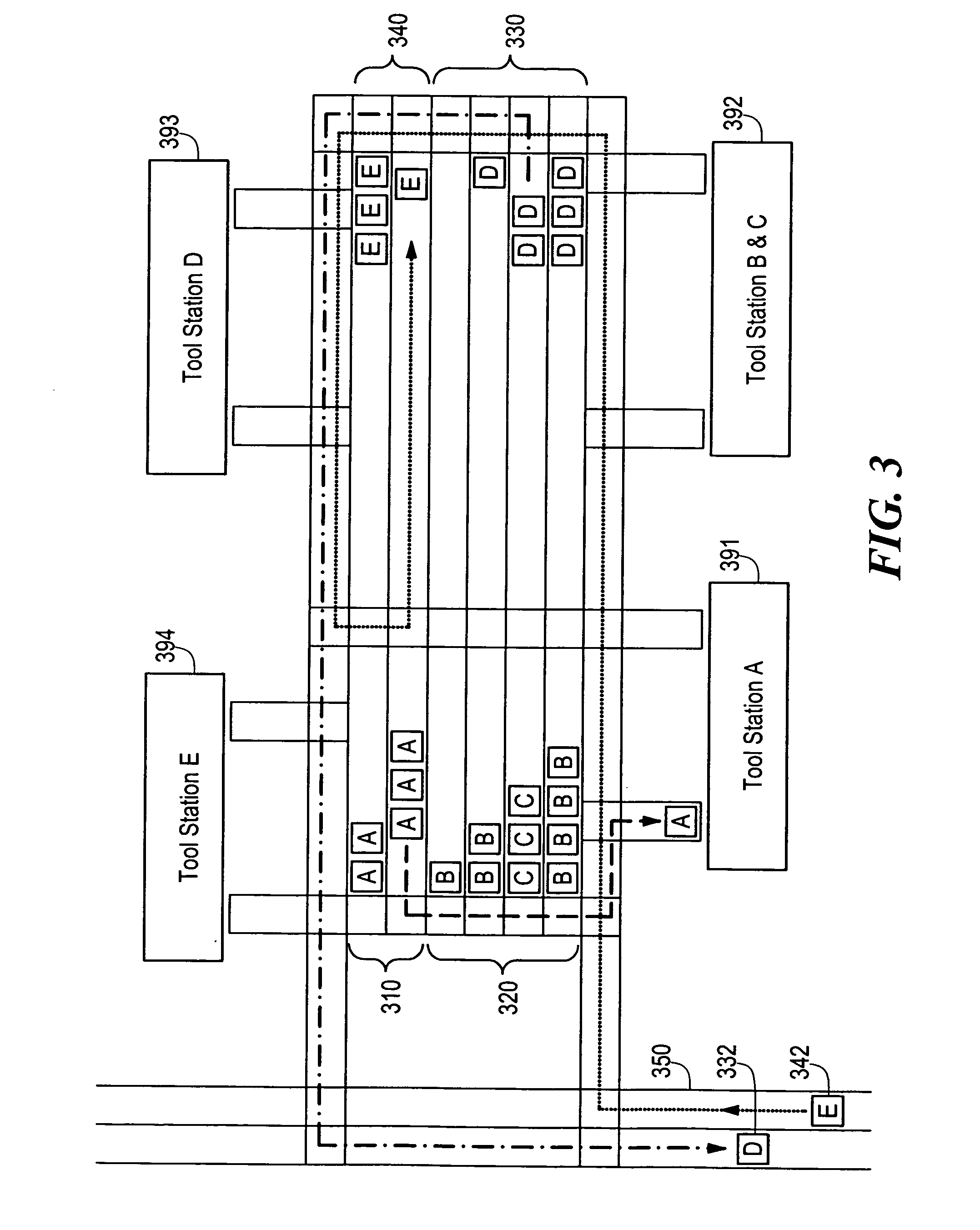
[0008] The presently disclosed system includes an easily configurable storage system which is particularly well-suited for use with clean-environment conveyors, such as those described in U.S. Pat. No. 6,047,812 to Horn et al, incorporated herein by reference. The storage system includes modular conveyor elements which may be provided parallel to and adjacent a ceiling mounted conveyor network. The conveyor elements may be provided as “one-way” paths which, when provided with plural transfer elements with respect to the path of the conveyor elements, can enable the circulation of a work-piece or a carrier of work-pieces from a storage matrix to a transfer path and back to the storage matrix. This avoids a problem with a needed work-piece being located in the middle of other not-needed work-pieces in the storage matrix.
[0009] In an alternative embodiment, plural storage conveyor elements may be provided parallel to one another. Adjacent storage conveyor elements may be used to realize storage loops, thus obviating the need for moving stored work-pieces onto the conveyor process path when accessing a subsequent work-piece. Further embodiments include the use of a single storage conveyor element within multiple loops of storage conveyor elements, where work-pieces of different types proceed in opposite directions when leaving the storage conveyor element. The modularity of the present system further enables the realization of plural, nested loops of storage conveyor elements in which work-pieces may be rapidly exchanged between loops of storage conveyor elements, rotated within a single loop of storage conveyor elements, or retrieved to a transfer path of the conveyor network or to a machine tool. Massively parallel storage solutions can be readily designed and implemented without the need for dedicated floor space.
[0010] Such varying embodiments may be provided as pre-configured systems, or with the provision of appropriate sensing mechanisms and control logic may be auto-configuring according to a variety of parameters including competing storage needs for various types of work-pieces, time of day, etc. With either centralized or distributed control circuits, either or both of which may be employed in the presently disclosed storage system, simultaneous relocation of multiple work-pieces provides a far more efficient storage solution as compared to that afforded by the robotic stockers of the prior art. The control logic may provide buffering of each machine tool in the system and / or storing work-in-process (WIP) at the machine tool that is ready to be received and processed as soon as the machine tool becomes available.
[0012] In the above mentioned industries, the manufacturing process is highly recursive, i.e. the WIP re-enters a machine tool many times after it has been processed elsewhere. Typically, there may be hundreds of process machine tools to go through and re-enter several times in a different sequential fashion for each work-piece. Additionally, several work-pieces may be concurrently handled. Process machine tools are often placed in a spatial array according to function rather than operating sequence. There may be several machine tools, in different parts of a factory, capable of performing the next sequential operation on the WIP lot. From the start of the manufacturing process to the finish, the WIP lot may spend one to two months in the factory while moving between machine tools. These factories are frequently called chaotic as a mathematical system. Applicants have discovered that such factories achieve significant throughput gains if the work-piece handling design is based on a conveyor network where each process machine tool is connected to or is on the conveyor network. Then, in this non-linear manufacturing environment, the control logic according to the present invention sends and pulls each WIP lot to the next process machine tool as soon as the WIP lot is finished at the previous manufacturing step. The control logic is based on asynchronous and independent movement of each WIP lot, which is only possible with a conveyor network capable of moving each WIP independently of the other now matter how close they are to each other. The control logic according to the present invention is particularly applicable to the concept of conveyor networks and Applicants specifically utilize conveyor networks for these clean manufacturing industries and take advantage of the productivity gain therethrough.
[0014] The inefficiencies of the presently known systems arise from the fact that there are not buffers / stockers immediately provided at the next machine tool. Because the vehicle cars are highly utilized for transport only, costly pile ups and bottle-necks often occur at the machine tool. Well known analytical solution of this problem and computer simulations show the serious drawbacks of this technique (see queuing theory, for example). Accordingly, the present invention is directed to solving these deficiencies in the known techniques by applying conveyor transport networks in conjunction with a native stocker and buffer at the machine tool for improving the machine tool utilization while maintaining the product cycle time as well as improving the financial costs in comparison to the known techniques.

Problems solved by technology

Historically, a conveyor methodology of transport has not been accepted in these industries, where ultra-clean handling of material is required.
As is evident, no parallel work-piece manipulations can be executed by the stocker robot while this storing activity is underway.
The same limitation to single work-piece manipulation exists when the stocker robot is in the process of retrieving a work-piece.
Another deficiency associated with stockers pertains to the amount of floor space which such systems typically occupy.
If multiple stockers are provided as a means for lessening the bottleneck in work-piece flow as compared to the use of a single stocker, that much more floor space is consumed.
The cost of the overall system is significantly raised as a consequence.

Method used


Image

  • Conveyorized storage and transportation system
  • Conveyorized storage and transportation system
  • Conveyorized storage and transportation system

Examples


Embodiment Construction

[0022] The conveyorized storage and transport system according to the embodiments of the present invention may be used in any type of processing industry requiring storage for maintaining inventories at multiple processing stations. The manufacture of semiconductor devices is one example of an industry that is particularly suited for the features provided by the storage and transport system according to the embodiments of the present invention. In the illustrations, various embodiments of the presently disclosed storage and transport system are referred to as a “field stocker.”

[0023] Carriers conveyed by a clean-environment conveyor system may be pallets carrying one or more individual work-pieces. Alternatively, the conveyor elements may transport the work-pieces themselves without the need for carriers. In a semiconductor manufacturing process, substrates are usually carried in a transport carrier, while in flat panel manufacturing, the work-pieces may ride in carriers or directly...


PUM


Abstract

A configurable storage system particularly suited for use with clean-environment conveyors is disclosed. The storage system includes modular conveyor track elements which may be provided parallel to and adjacent a ceiling mounted conveyor highway. Conveyor elements may be provided as one-way paths which, when provided with plural transfer elements with respect to a conveyor highway, enable the rotation of a work-piece from a storage matrix to a transfer path and back to the storage matrix. Adjacent storage conveyor elements may be used to realize loops of storage elements. A single storage conveyor element may be shared by multiple loops of storage elements. The modularity of the present system enables the realization of plural, nested loops of storage elements. Control over such systems may be provided locally, centrally or some combination of both, and may adjust the behavior of individual storage conveyor elements based on a variety of factors.

Description

CROSS REFERENCE TO RELATED APPLICATIONS [0001] This application is a continuation application of U.S. patent application Ser. No. 10 / 433,828, filed Jun. 5, 2003 which claims priority of U.S. Provisional Application No. 60 / 266,715 filed Feb. 6, 2001.STATEMENT REGARDING FEDERALLY SPONSORED RESEARCH OR DEVELOPMENT [0002] N / A BACKGROUND OF THE INVENTION [0003] In clean-environment manufacturing industries, such as the manufacturing of flat panel display devices and semiconductors, there is a need to handle large amounts of in-process inventories. In these industries, discrete vehicle-type transports, such as monorail vehicles or automated guided vehicles, have prevailed, especially in the front-end of clean manufacturing processes. Manually operated vehicle-type carts have served such industries as well. [0004] Historically, a conveyor methodology of transport has not been accepted in these industries, where ultra-clean handling of material is required. Recent advances in conveyor techn...

Claims


Application Information

Patent Timeline
Patent Type & Authority Applications(United States)
IPC IPC(8): B65G49/06H01L21/00H01L21/677
CPCB65G49/064B65G49/068H01L21/67727H01L21/67276B65G2249/02
Inventor HORN, GEORGE
Owner MIDDLESEX GEN INDS MESNE
Why Eureka
Try Eureka