Flat heat pipe with hook capillary tissue

a capillary tissue and heat pipe technology, applied in the field of heat pipes, can solve the problems of poor thermal conduction efficiency of the heat pipe, insufficient supply of working fluid, and reduced capillary tissue installed on the surface at the bottom of the pipe,

Inactive Publication Date: 2011-05-05
KUNSHAN JUZHONG ELECTRONICS
View PDF10 Cites 30 Cited by
  • Summary
  • Abstract
  • Description
  • Claims
  • Application Information

AI Technical Summary

Benefits of technology

[0011]The present invention has the effect of storing sufficient working fluid at the evaporation section of the heat pipe by means of th

Problems solved by technology

Although such heat pipe can perform a gas-liquid phase change with the heat produced by a heat source, yet the amount of capillary tissue installed onto a surface at the bottom wall of the pipe is reduced significantly due to the small gas passage in the pipe with an increasingly smaller size, and the internal surface of the capillary tissue is a rough surface which further constitutes an o

Method used


Image

  • Flat heat pipe with hook capillary tissue
  • Flat heat pipe with hook capillary tissue
  • Flat heat pipe with hook capillary tissue

Examples


Embodiment Construction

[0020]The technical characteristics, features and advantages of the present invention will become apparent in the following detailed description of the preferred embodiments with reference to the accompanying drawings. The drawings are provided for reference and illustration only, but not intended for limiting the present invention.

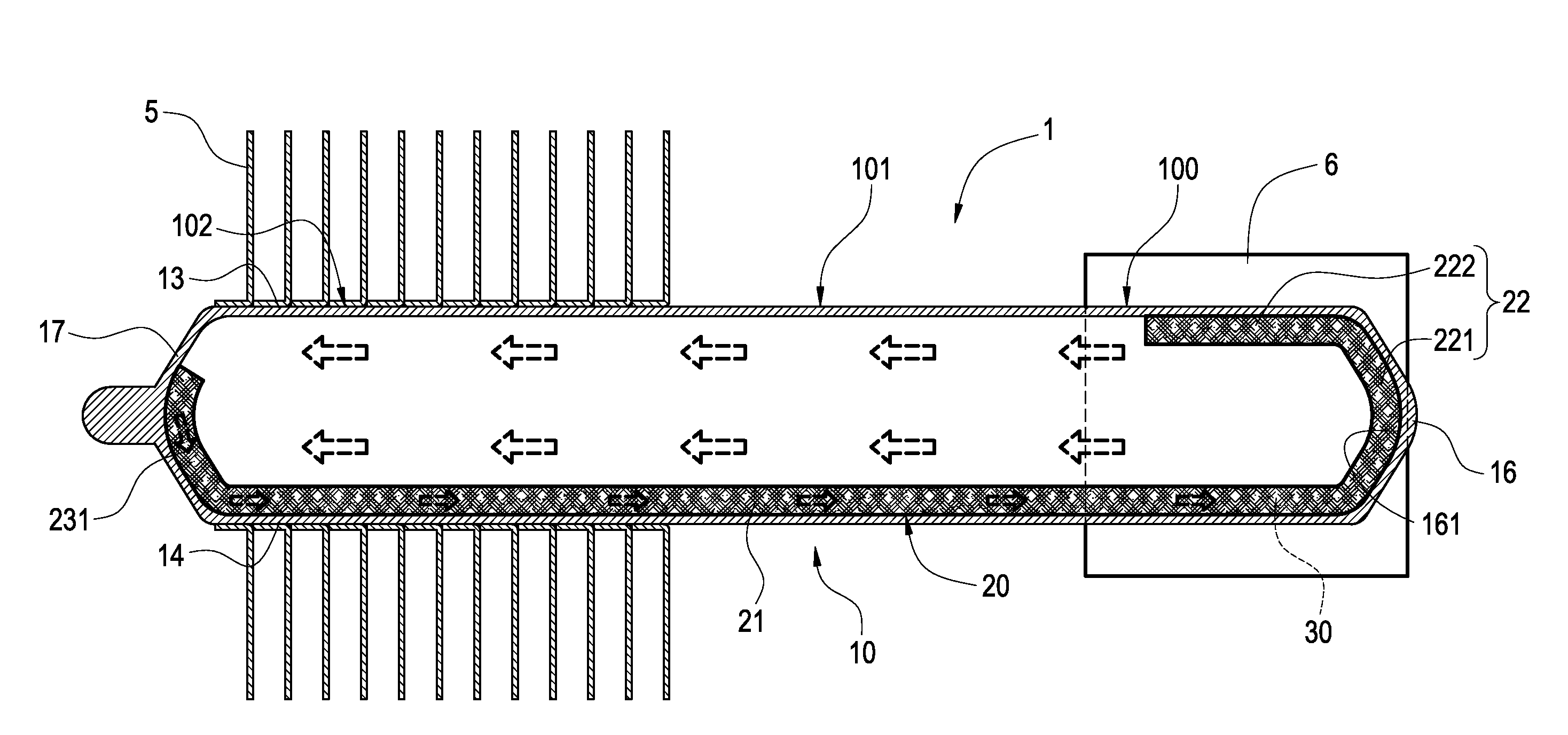
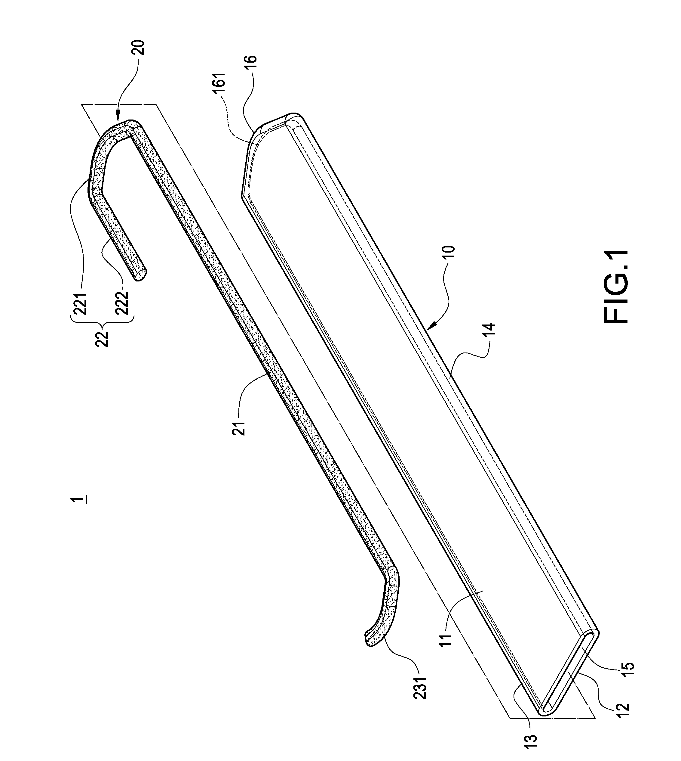
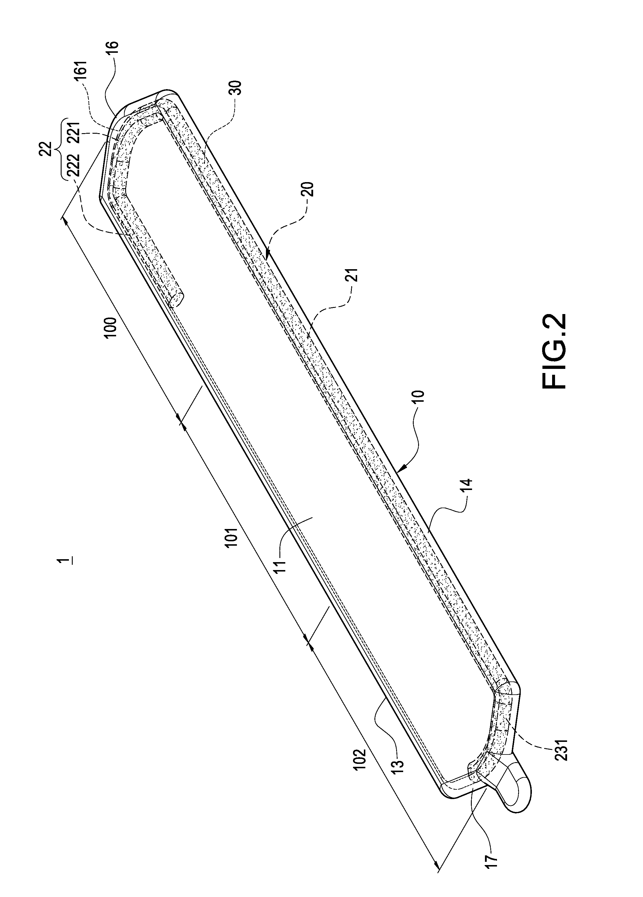
[0021]With reference to FIGS. 1 to 4 for a flat heat pipe with hook capillary tissue in accordance with the present invention, the heat pipe 1 comprises a metal pipe 10, a capillary tissue 20 and a working fluid 30.

[0022]The metal pipe 10 is made of a material having a high thermal conductivity such as copper, and manufactured into a flat shape, and the flat shape metal pipe 10 is formed by enclosing an upper panel 11, a lower panel 12, a left sidewall 13 and a right sidewall 14, and a hollow chamber 15 is formed in the metal pipe 10, and both left and right sidewall 13, 14 are in a semicircular shape. In addition, an end of the metal pipe 10 is soldered ...


PUM


Abstract

A flat heat pipe with hook capillary tissue includes a metal pipe, a capillary tissue and working fluid. The metal pipe is in a flat shape and formed by enclosing two opposite panels and two opposite sidewalls, and a hollow chamber is formed in the metal pipe. The capillary tissue is in the shape of a long strip, and includes having a hook formed at an end of the capillary tissue, and the capillary tissue is contained in the hollow chamber and attached onto one of the sidewalls and abutted between two sidewalls, and a working fluid is filled into the hollow chamber and adhered to the capillary tissue, so that the stability of fixing the capillary tissue into the metal pipe can be improved, and the retention quantity of the working fluid at an end of the pipe can be maintained.

Description

BACKGROUND OF THE INVENTION[0001]1. Field of the Invention[0002]The present invention relates to a heat pipe, and more particularly to a flat heat pipe with a hook capillary tissue.[0003]2. Description of Prior Art[0004]As a central processing unit (CPU) of a computer comes with an increasingly higher speed, and electronic products tends to have a light, thin, short and compact design, a conventional heat dissipation device composed of an aluminum extrusion heat sink and a fan can no longer meet the user requirements anymore, and thus manufacturers keep developing new heat pipes with a higher thermal conduction efficiency and combining heat pipes with the heat sink to overcome present existing heat dissipation problems. However, the structural design of the interior of the heat pipe relates to flows of gas and liquid in the heat pipe and an available using space, and thus the inventor of the present invention focused on the aforementioned problem to design and develop a heat pipe to...

Claims


Application Information

Patent Timeline
IPC IPC(8): F28D15/04
CPCF28D15/0233F28D15/046H01L23/427H01L2924/0002H01L2924/00
Inventor HUANG, YU-POKUO, TUNG-JUNG
Owner KUNSHAN JUZHONG ELECTRONICS
Why Eureka
Try Eureka