
Door catch for sliding doors of motor vehicles

a technology for sliding doors and motor vehicles, which is applied in the direction of doors, wing accessories, manufacturing tools, etc., can solve the problems of short life of running rollers, severe load on door catch bearings, and difficult assembly

Inactive Publication Date: 2003-01-16
ESCHA
View PDF7 Cites 4 Cited by
  • Summary
  • Abstract
  • Description
  • Claims
  • Application Information

AI Technical Summary

Benefits of technology

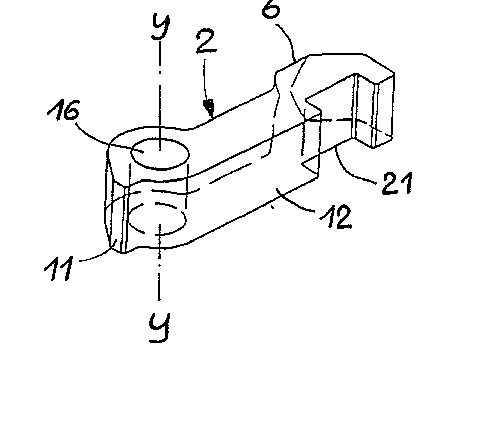
[0014] The present invention is completely independent of the arrangement of any running mechanism, such as running rollers. Consequently, running rollers and their bearings that are present are not subjected to loading. The door catch can be fitted easily since there are various fitting options: the direction of force of the system, i.e. of the lever, can be either perpendicular or horizontal relative to the direction of travel of the sliding door, for example relative to a running rail of the sliding door. A compression spring or a leg spring can be used, depending on space conditions. In contrast to the known latching roller, however, both the latching cam and the nose can have different shapes, in particular cross-sectional profiles, making it possible to vary the operation of the door catch very widely and hence meet very different customer requirements, whether as regards the actuating force, the actuating travel or the holding force. The actuating force, the entry or withdrawal force respectively required on the sliding door is kept low. The overall mechanism required, especially the spring-loaded holding arm, can be made compact, in particular short, and hence economical in terms of space and materials, and can be mounted easily from the front, from the outside of the body. The latching cam is secured on the sliding door at a suitable location, preferably on a traveling carriage, which is usually present, or on a traveling-carriage arm carrying the latter.
[0015] In a preferred embodiment, the nose has two ramps and a tip situated between them. Through use of the ramps, a largely uniform and jerk-free motion is obtained, having the effect of braking the door. This gentle transition can be further assisted by the fact that the tip is rounded in the direction of the ramps.
[0016] If the tip is also rounded transversely to the direction of travel, even a slight angular offset of the latching members, nose and latching cam involved does not impair the latching function. To this extent, large dimensional tolerances can be provided for the fitting of the latching members or the holders carrying them, and adjustment or readjustment work can be completely eliminated. To make both the abovementioned rounded portions the same, the tip can have a spherical surface.
[0018] On the other side of the latching arrangement, on the counter-latching member, the latching cam can likewise have a different geometry in order to enable the "feel" when actuating the sliding door to be matched to a large extent to the customer's requirements. For instance, the latching cam can have an entry ramp and a holding ramp and a tip region situated between them, the tip region can be designed as a straight line in the direction of travel of the sliding door, and the straight tip region can merge into the ramps via rounded portions. Fine coordination of the forces involved in latching is possible by coordinating the shape and height of the cam, i.e. its tip region, its ramps and its rounded portions.
[0020] To gain momentum for releasing the latching arrangement when the sliding door is open, the holding ramp is adjoined by a traversing section extending in the direction of travel. Through the use of this traversing section, the latching of the nose on the holding arm by the holding force applied to the spring in addition to the preloading is fully assured. However, the run-up of the sliding door across this traversing section allows the holding ramp to be overcome more effectively. To brake the nose and hence the sliding door in the direction of maximum opening of the sliding door, the traversing section is adjoined by a raised portion, which can comprise a ramp. The raised portion does not have to serve as an end stop for the sliding door if a customary separate stop designed to withstand an appropriate loading is provided at some other point on the sliding door and its guide.
[0023] If the holding arm or at least its nose and / or the latching cam comprises an abrasion-resistant plastic with good sliding properties, there is only little rubbing noise and only little wear.

Problems solved by technology

This door catch imposes severe loading on the bearings of the running rollers of the traveling carriage, owing namely to the very high spring force of the leg spring due to the preloading, it being necessary for this spring force to be sufficiently high to bring about an adequate, safe holding force for the open sliding door.
Under this heavy and shock-type loading, the life of the running rollers is short, especially when the doors are opened very often and the door catch is consequently used very often, as is the case, for example, with commercial use of buses, delivery vehicles and the like.
Moreover, assembly is difficult since it must take place from the rear side of the running rail and, for this purpose, requires an opening in the running rail, at least for the latching roller.
A door catch of this kind is complex and consequently expensive to produce.
Moreover, it has little capacity for adaptation to the wishes of the user.

Method used


Image

  • Door catch for sliding doors of motor vehicles
  • Door catch for sliding doors of motor vehicles
  • Door catch for sliding doors of motor vehicles

Examples


Embodiment Construction

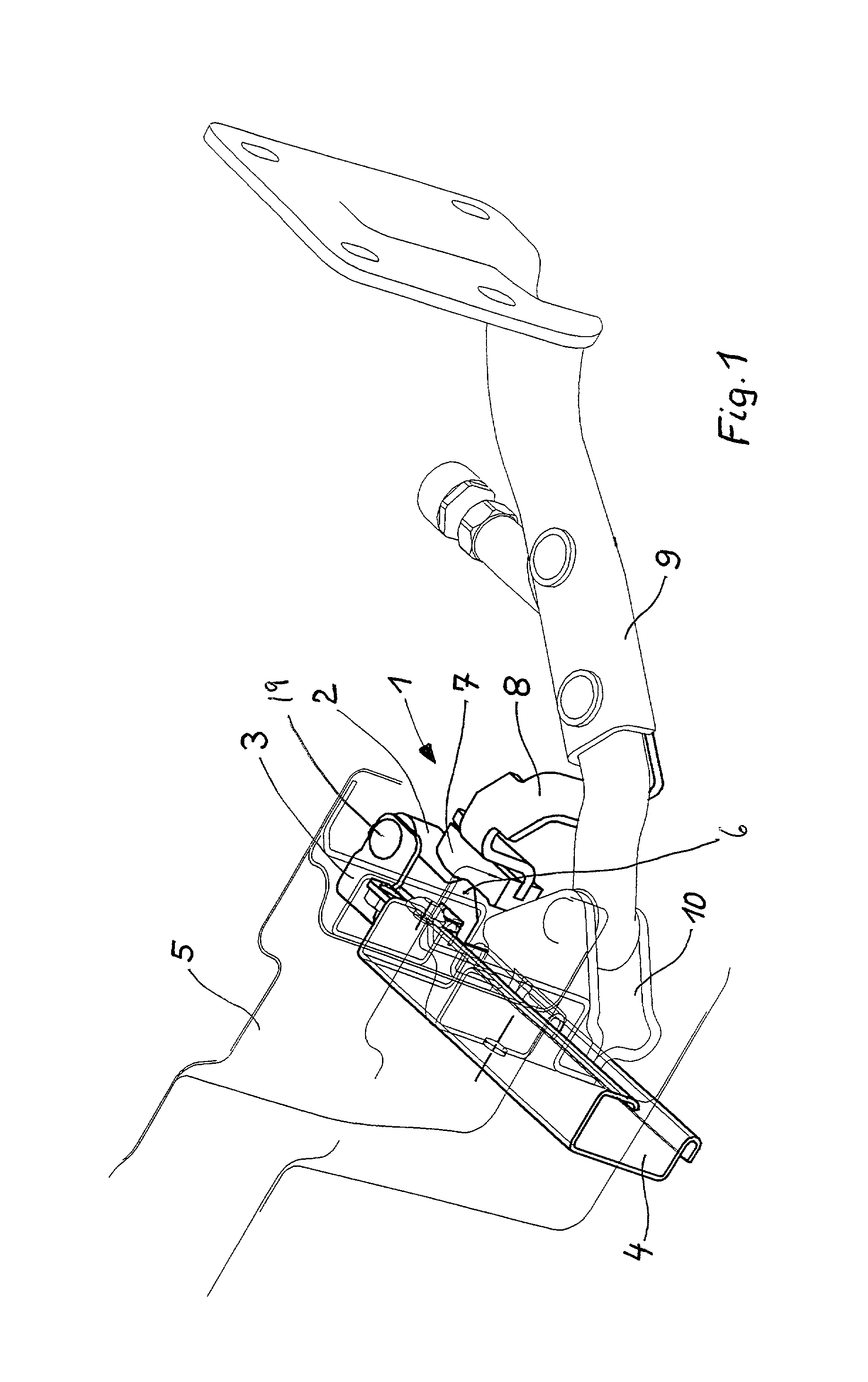
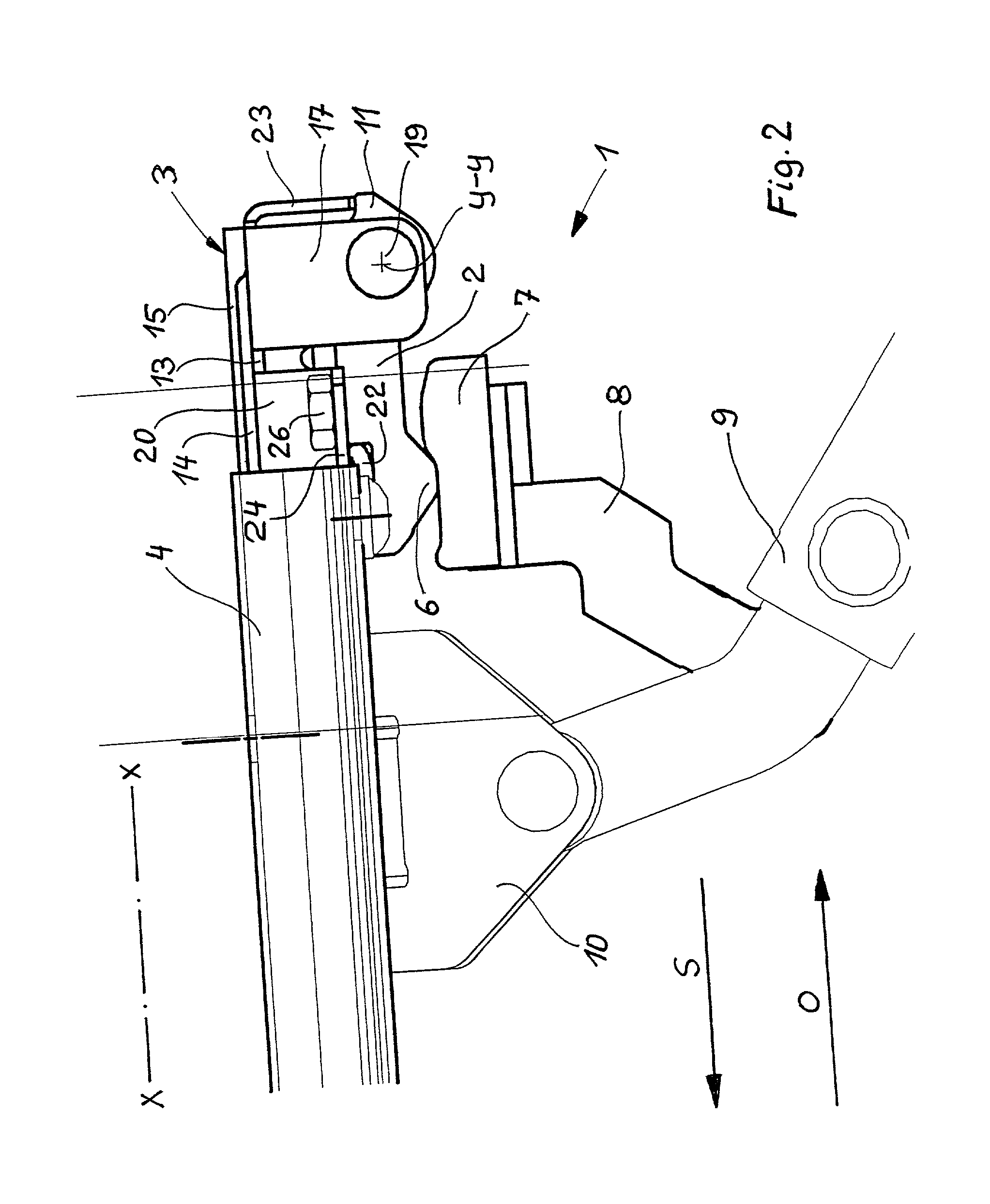
[0033] As shown in FIGS. 1 and 2, the door catch 1 comprises a holding arm 2, which is mounted pivotably in a holder 3. The holder 3 is secured at the rear end of a running rail 4, which is connected to the body 5.

[0034] The holding arm 2 interacts through an integrally formed nose 6 with a latching cam 7, which acts as a counter-latching member, to produce a locking effect. For this purpose, the latching cam 7 is connected indirectly, namely via a traveling carriage arm 9, to a sliding door via a holder 8 (See FIGS. 1, 2 and 7). The traveling carriage arm 9 connects the sliding door to the running rail 4 via a pivotably connected traveling carriage 10. The traveling carriage 10 is of known construction and guides the sliding door into the open or closed position during its displacement on the body. The direction or principal direction of travel of the sliding door is denoted by X-X. The door catch 1 exerts a locking action between the sliding door and the body 5 in this direction o...


PUM


Abstract

A door catch for a sliding door of a motor vehicle includes a holding arm, with the holding arm being secured on a running rail of the sliding door using a holder and being pivotable against a preloaded spring. The catch has a latching member, the latching member being a nose which is arranged on the holding arm, and a counter-latching member, the counter-latching member being a latching cam which is acting transversely to the direction of travel of the sliding door. In the open position of the door, the holding arm latches, through said latching member, with said counter-latching member.

Description

[0001] Priority to German Patent Application No. 101 33 938.0, filed Jul. 12, 2001 and hereby incorporated by reference herein, is claimed.BACKGROUND INFORMATION[0002] The present invention relates to a door catch for sliding doors of motor vehicles, with a holding arm, which is secured on the running rail of the sliding door using a holder, can be pivoted against a preloaded spring and, in the open position of the sliding door, latches using a latching member with a counter-latching member arranged on the sliding door.[0003] There are special requirements of door catches for sliding doors on vehicles: first of all, they should hold the sliding door in the open position with defined entry and withdrawal forces. At the same time, the sliding door should be held securely even when the vehicle is standing in an unfavorable way, e.g. at an angle, to exclude the possibility of accidents, especially due to sliding doors rolling back into the closed position. The actuating force for comple...

Claims


Application Information

Patent Timeline
IPC IPC(8): E05C17/22B60J5/04E05C17/60
CPCE05C17/60E05D13/04Y10T16/27E05Y2201/218E05Y2201/474E05Y2900/531
Inventor KINDERMANN, THOMAS
Owner ESCHA
Learn More