
Aligning and Assembling Method of Stereoscopic Display Device

a stereoscopic display device and assembling method technology, applied in the direction of optics, instruments, optical elements, etc., can solve the problems of lc panel significantly affecting the 3-d image quality of the stereoscopic display device with a lenticular lens, inaccurate 3-d images displayed on the stereoscopic display device, and inability to convey 3-d depth to the viewer, so as to achieve efficient overcome the effect of improving the image quality and the manufacturing productivity of the stereoscopic display

Inactive Publication Date: 2013-07-11
CHUNGHWA PICTURE TUBES LTD
View PDF2 Cites 4 Cited by
  • Summary
  • Abstract
  • Description
  • Claims
  • Application Information

AI Technical Summary

Benefits of technology

This patent describes a way to make a better quality stereoscopic display using a lens called a lenticular lens. The method helps to control the image quality by aligning and assembling the display components, which improves the image quality and increases manufacturing productivity. This allows for a better overall experience for the user when viewing the display.

Problems solved by technology

That is, when users watch the stereoscopic display device utilizing the naked-eye display technique outside the specific viewing range, 3-D images displayed on the stereoscopic display device may be formed inaccurately, and moreover, the stereoscopic display device is unable to convey 3-D depth to the viewer.
That is, the assembly precision of the lenticular panel and the LC panel may significantly affect the 3-D image quality of the stereoscopic display device with a lenticular lens.
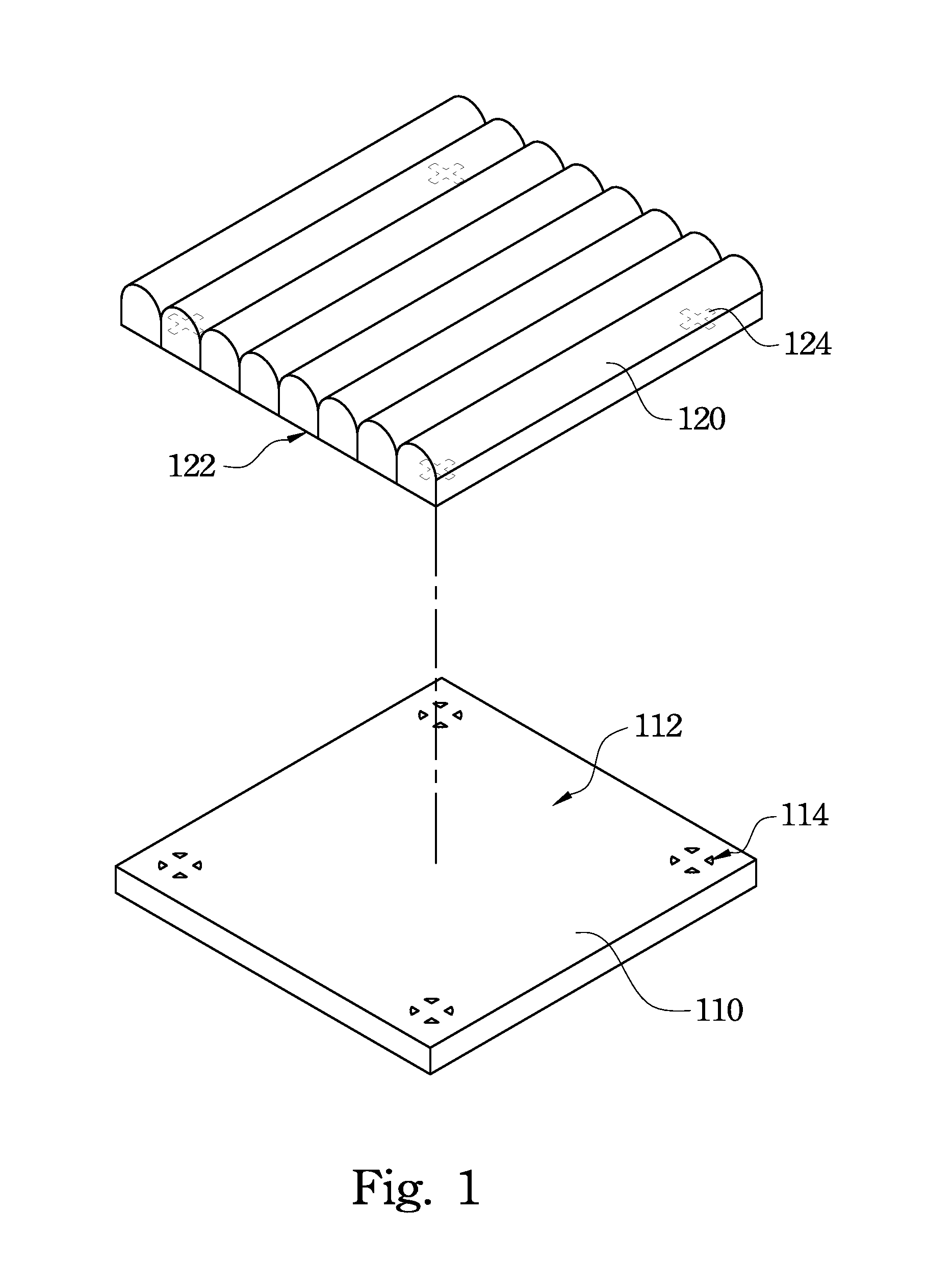
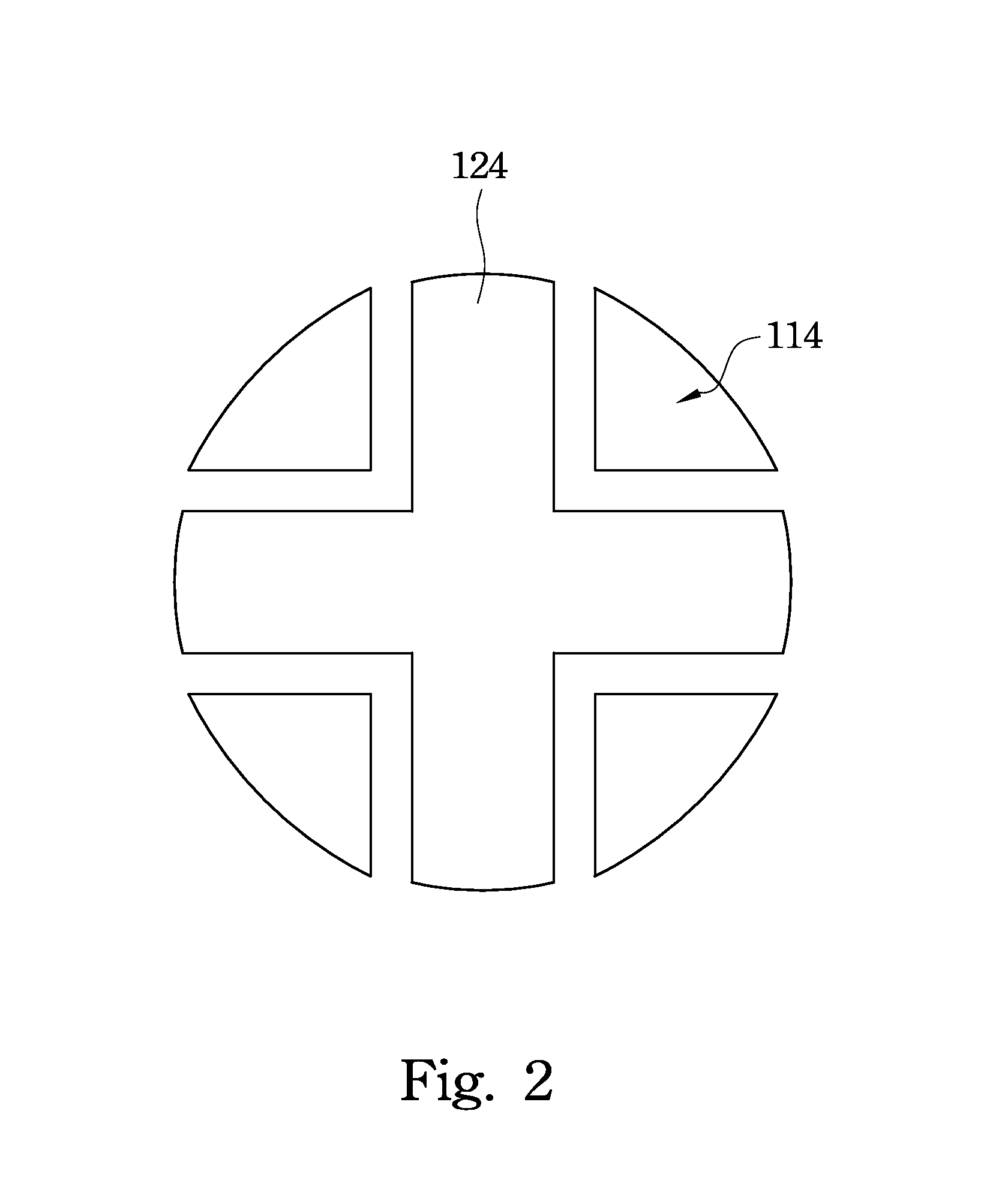
However, due to manufacturing and material differences of the LC panels 110 and the lenticular panels 120 of different stereoscopic display devices, the image quality of a stereoscopic display device with a lenticular lens cannot be controlled precisely by relying solely on an assembly method utilizing the marks 114 and the marks 124.
Therefore, the image quality and the manufacturing productivity associated with the stereoscopic display device with a lenticular lens cannot be easily improved.

Method used


Image

  • Aligning and Assembling Method of Stereoscopic Display Device
  • Aligning and Assembling Method of Stereoscopic Display Device
  • Aligning and Assembling Method of Stereoscopic Display Device

Examples


Embodiment Construction

[0039]In the following detailed description, for purposes of explanation, numerous specific details are set forth in order to provide a thorough understanding of the disclosed embodiments. It will be apparent, however, that one or more embodiments may be practiced without these specific details. In other instances, well-known structures and devices are schematically shown in order to simplify the drawings.

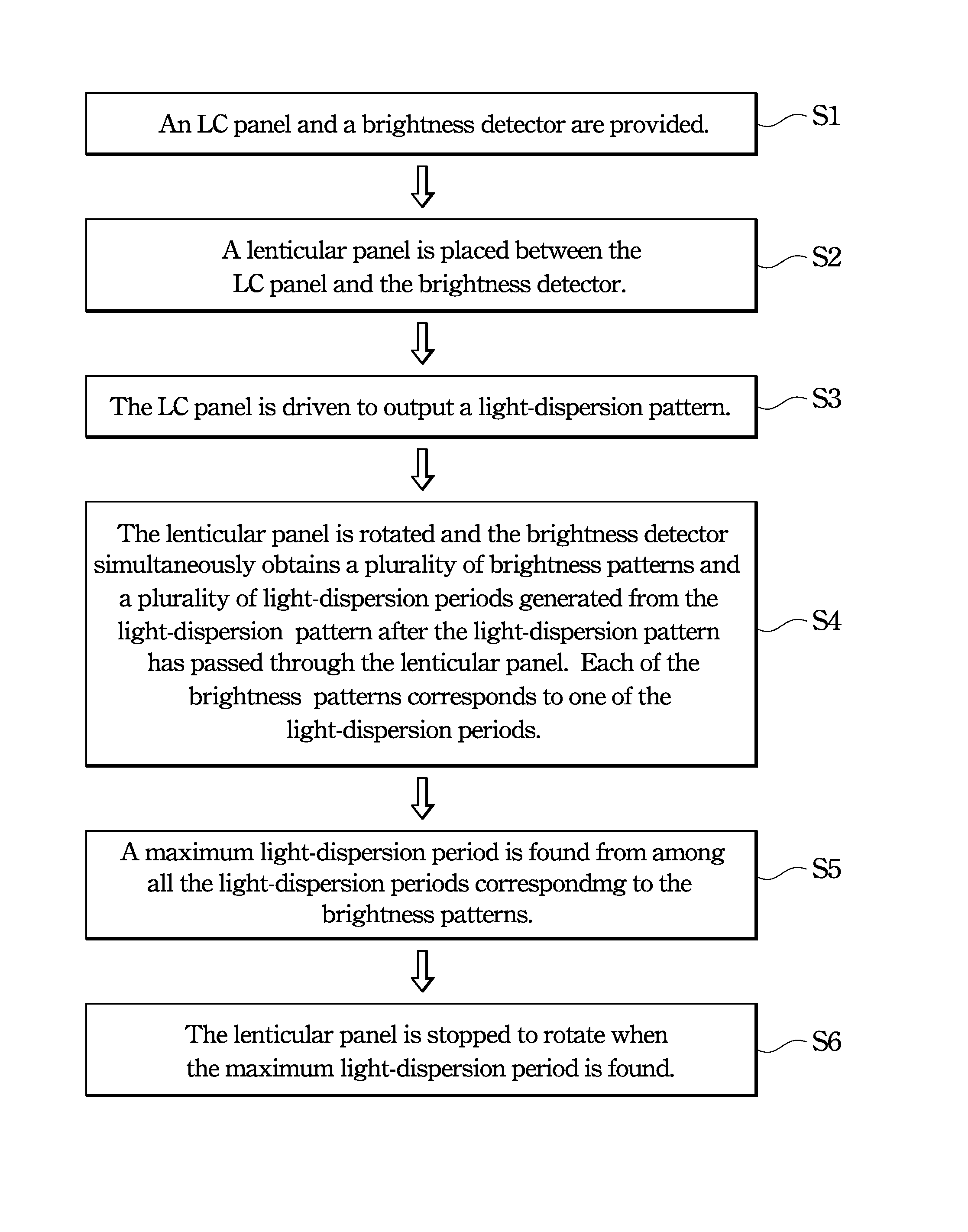
[0040]FIG. 3 is a perspective view of an LC panel 210 and a lenticular panel 220 of a stereoscopic display device which is used to describe an aligning and assembling method of a stereoscopic display device according to an embodiment of the present invention. FIG. 4 is a flow chart of an aligning and assembling method of a stereoscopic display device of an embodiment of the present invention. The aligning and assembling method of a stereoscopic display device includes steps that will be outlined below with reference to FIGS. 3 and 4.

[0041]In step S1, the LC panel 210 and a brightne...


PUM

PropertyMeasurementUnit
angleaaaaaaaaaa
driving voltageaaaaaaaaaa

Abstract

An aligning and assembling method of a stereoscopic display device is provided and includes providing a liquid crystal (LC) panel and a brightness detector. A lenticular panel is placed between the LC panel and the brightness detector. The LC panel is driven to output a light-dispersion pattern. The lenticular panel is rotated and the brightness detector obtains a plurality of brightness patterns and a plurality of light-dispersion periods generated from the light-dispersion pattern after the light-dispersion pattern has passed through the lenticular panel. The brightness patterns correspond respectively to the light-dispersion periods. A maximum light-dispersion period is found from the light-dispersion periods. The lenticular panel is stopped to rotate when the maximum light-dispersion period is found.

Description

RELATED APPLICATIONS[0001]This application claims priority to Taiwan Application Serial Number 101100952, filed Jan. 10, 2012, which is herein incorporated by reference.BACKGROUND[0002]1. Technical Field[0003]The present disclosure relates to an aligning and assembling method, and more particularly to an aligning and assembling method of a stereoscopic display device.[0004]2. Description of Related Art[0005]There are different types of stereoscopic display devices. For example, a stereoscopic display device may utilize a naked-eye display technique, a lenticular lens display technique, or a parallax barrier display technique. With respect to the stereoscopic display device utilizing the naked-eye display technique, such a stereoscopic display device needs to be watched in a specific viewing range to ensure 3-dimensional (3-D) display performance. That is, when users watch the stereoscopic display device utilizing the naked-eye display technique outside the specific viewing range, 3-...

Claims


Application Information

Patent Timeline
Patent Type & Authority Applications(United States)
IPC IPC(8): G02F1/1337G02B30/28
CPCG02F1/1337G02B27/22G02B27/2214G02B30/28G02B30/27
Inventor LIAO, JIAN-DAHUANG, CHUN-MINGLEE, HUAN-TING
Owner CHUNGHWA PICTURE TUBES LTD
Learn More