Desiccating container

a container and desiccating technology, applied in the field of containers, can solve the problems of insufficient force between respective barrier points or barrier rings, inability to design structures well, and inability to effectively overcome the force difference between them

Inactive Publication Date: 2014-07-29
TSAI FENG DER
View PDF12 Cites 5 Cited by
  • Summary
  • Abstract
  • Description
  • Claims
  • Application Information

AI Technical Summary

Benefits of technology

[0008]Thus the present invention aims to improve the aforementioned defects, to design a novel structure for a can and to provide a novel desiccating container that is capable to effectively overcome the aforementioned defects and further has an air-sealed effect.
[0009]The desiccating container provided by the present invention has an annular ring, cooperated with the sealing boundary, disposed along the edge near the opening of the body for preventing the burst or protrusion of the cap. With use of an adequate desiccant, a desiccating container with air-sealed capability is accordingly provided.

Problems solved by technology

However, with respect to the structure for a conventional air-sealed can, a barrier point or a barrier ring is usually disposed on body portion of the conventional air-sealed can, from which defects are accordingly derived.
The derived defects are a consequence resulted from an ill design on structure or a non-circle product having a body biased from circle.
As to the ill design on structure, it results in discrepancy for the force between respective barrier points or barrier ring with respect to the sealing ring on the cap.
As to the barrier ring, though it overcomes the defects existing in the use of barrier points to avoid the protrusion or burst by contacting with the cap in line-contacting instead of point-contacting, it also encounters troubles while the pressure or temperature in the environmental is significantly varied, since the air existing in the air-sealed can will proportionally expand its volume with respect to ascension of the temperature, which finally results in a burst, once the tolerance limitation ceiling is reached.
Furthermore, there are many reasons to cause a non-circle product, including the bad precision during machining, the ill plastic injection mold, the collision during cargo delivering and the shrinkage due to temperature variation.
Thus, the barrier ring can not tightly resist to the cap, so that the can not be sealed accordingly.

Method used


Image

  • Desiccating container
  • Desiccating container
  • Desiccating container

Examples


Embodiment Construction

[0038]The present invention will now be described more specifically to the following embodiments. However, it is to be noted that the following descriptions of preferred embodiments of this invention are presented herein for the purposes of illustration and description only; it is not intended to be exhaustive or to be limited to the precise form disclosed.

[0039]Moreover, in order to provide clearer descriptions to facilitate easily understanding of the present invention, the parts of the drawing do not draw in accordance with their relative sizes. Some sizes and scales have been exaggerated. The parts of unrelated details are not drawn completely to simplify the drawing.

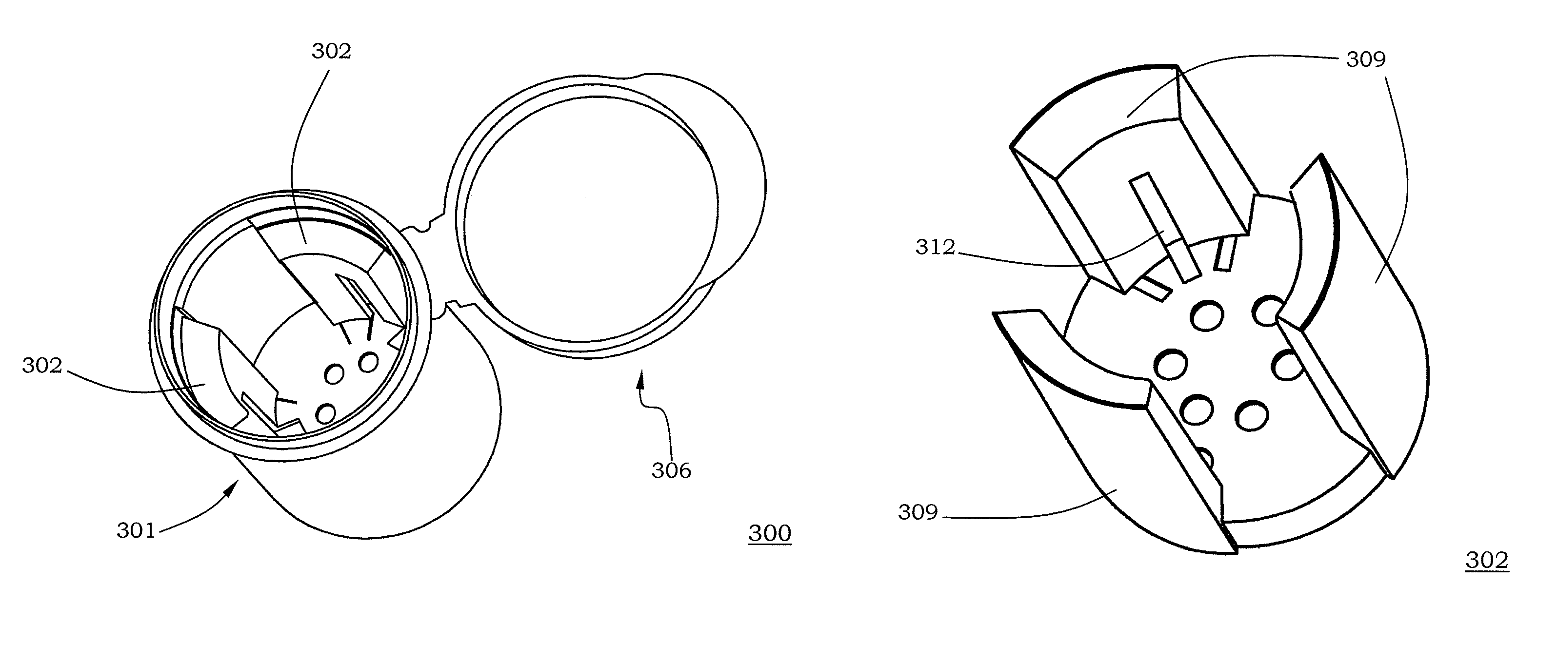
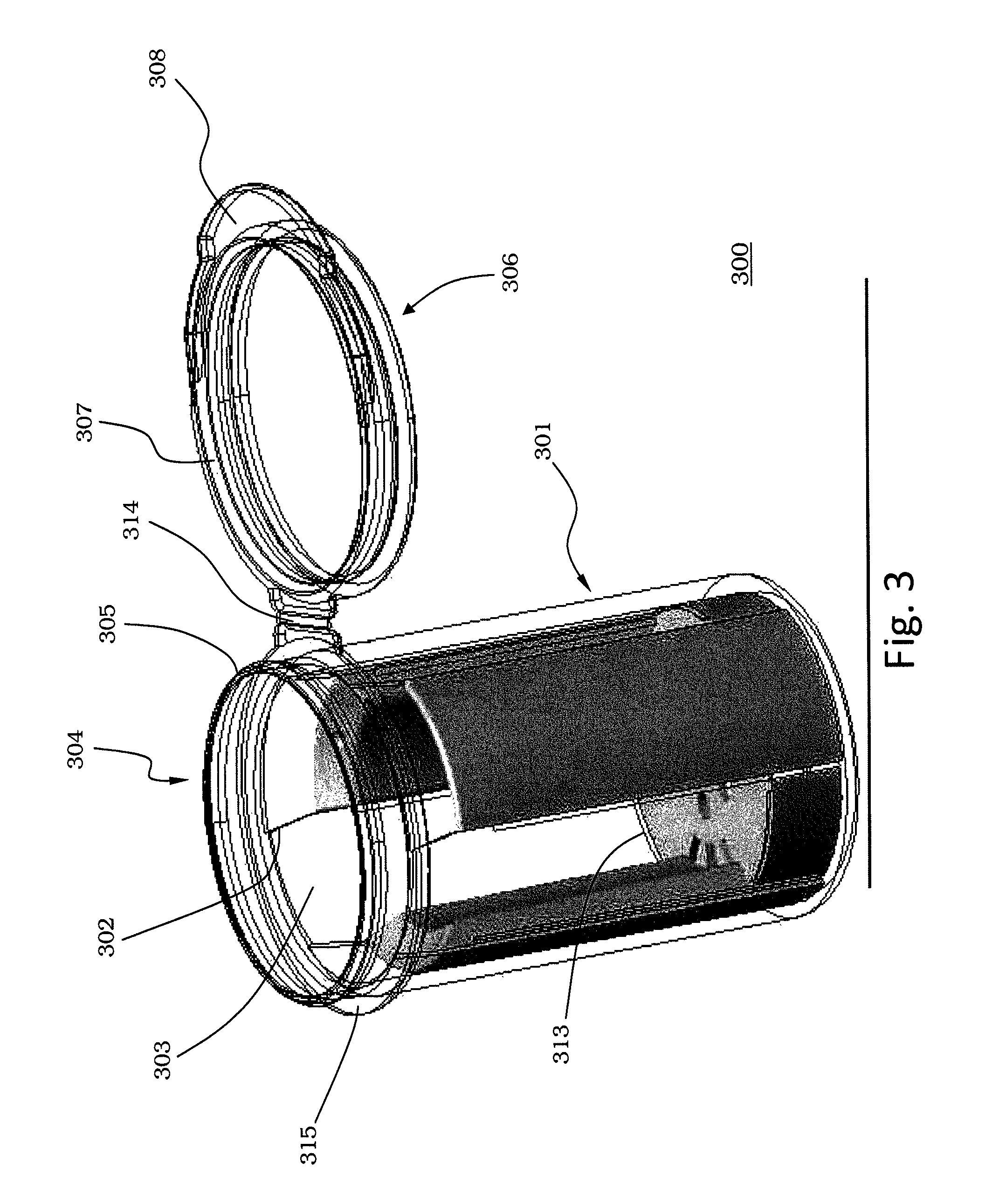
[0040]Please refer to FIG. 3, which is a diagram illustrating the desiccating container according to the present invention. The desiccating container 300 includes a body 301 (termed as outer can or outer bottle equivalently) and an insert (termed as inner can or inner bottle equivalently) and the insert 302 is fixed...


PUM


Abstract

A desiccating container is provided in the present invention. The desiccating container including an outer can; and an inner can configured in the outer can and having a wall with a containing space and a desiccant is contained in the containing space.

Description

FIELD OF THE INVENTION[0001]The invention is related to a container, and more particularly to a desiccating or a moisture-absorbing container.BACKGROUND OF THE INVENTION[0002]In order to preserve a glucose strip, a reagent or a drug for a long period, these items are usually reserved in an air-sealed can for preventing being moistened and for ensuing quality thereof. There are currently various kinds of air-sealed devices over the market, including the mentioned air-sealed based devices, a vacuum based devices or an air-sealed devices with desiccant function.[0003]However, with respect to the structure for a conventional air-sealed can, a barrier point or a barrier ring is usually disposed on body portion of the conventional air-sealed can, from which defects are accordingly derived. The derived defects are a consequence resulted from an ill design on structure or a non-circle product having a body biased from circle. As to the ill design on structure, it results in discrepancy for ...

Claims


Application Information

Patent Timeline
Patent Type & Authority Patents(United States)
IPC IPC(8): B65D81/26F17C11/00
CPCB65D81/266B65D43/162B65D2543/00092B65D2543/00296B65D2543/00537B65D2543/00629B65D2543/00685B65D2543/00731B65D2543/00796B65D2543/00842
Inventor CHANG, YI MINGHSU, CHENG TENG
Owner TSAI FENG DER
Why Eureka
Try Eureka