Railway vehicle and method for operating vehicle

a technology for operating vehicles and railway vehicles, applied in locomotives, transportation and packaging, instruments, etc., can solve the problems of reducing the maximum number of passengers on the railway vehicle, reducing the cabin space, and serious environmental problems, and achieve the effect of reducing the micropressure wav

Inactive Publication Date: 2005-06-30
HITACHI LTD
View PDF5 Cites 20 Cited by
  • Summary
  • Abstract
  • Description
  • Claims
  • Application Information

AI Technical Summary

Benefits of technology

[0013] Thus, the present invention enables to reduce the micropressure waves generated in a tunnel by taking in air through inlets formed to the surface of the nose portion of the leading vehicle.

Problems solved by technology

In this case, the leading vehicle serves as a piston in the tunnel, and this relationship between the leading vehicle and the tunnel can cause a serious environmental problem.
However, this diminishes the cabin space, and thus, the maximum number of passengers on the railway vehicle is reduced.
The prior art methods were only able to partially solve the contradicting tasks of reducing micropressure waves and ensuring the capacity of passengers on the leading vehicle.

Method used


Image

  • Railway vehicle and method for operating vehicle
  • Railway vehicle and method for operating vehicle
  • Railway vehicle and method for operating vehicle

Examples


embodiment 1

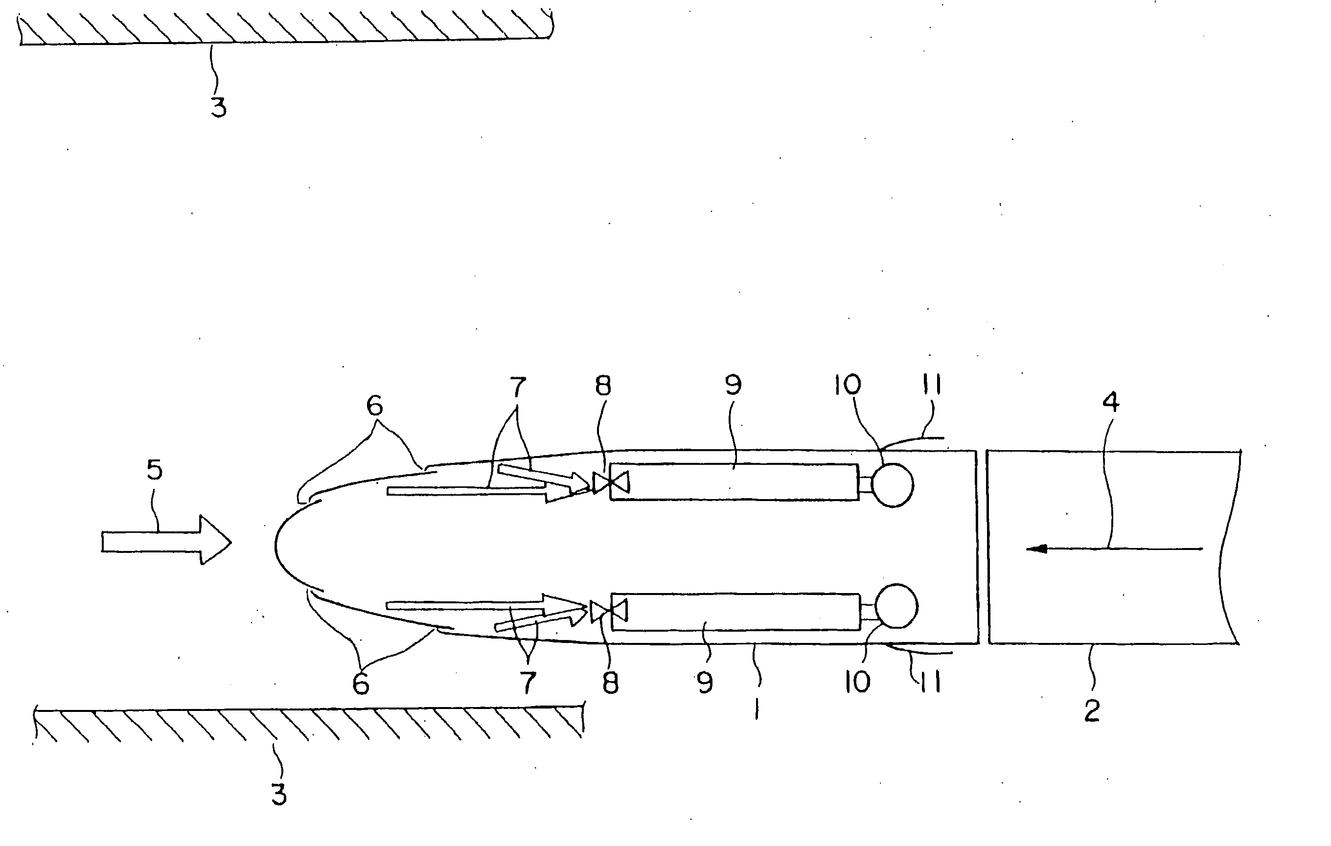
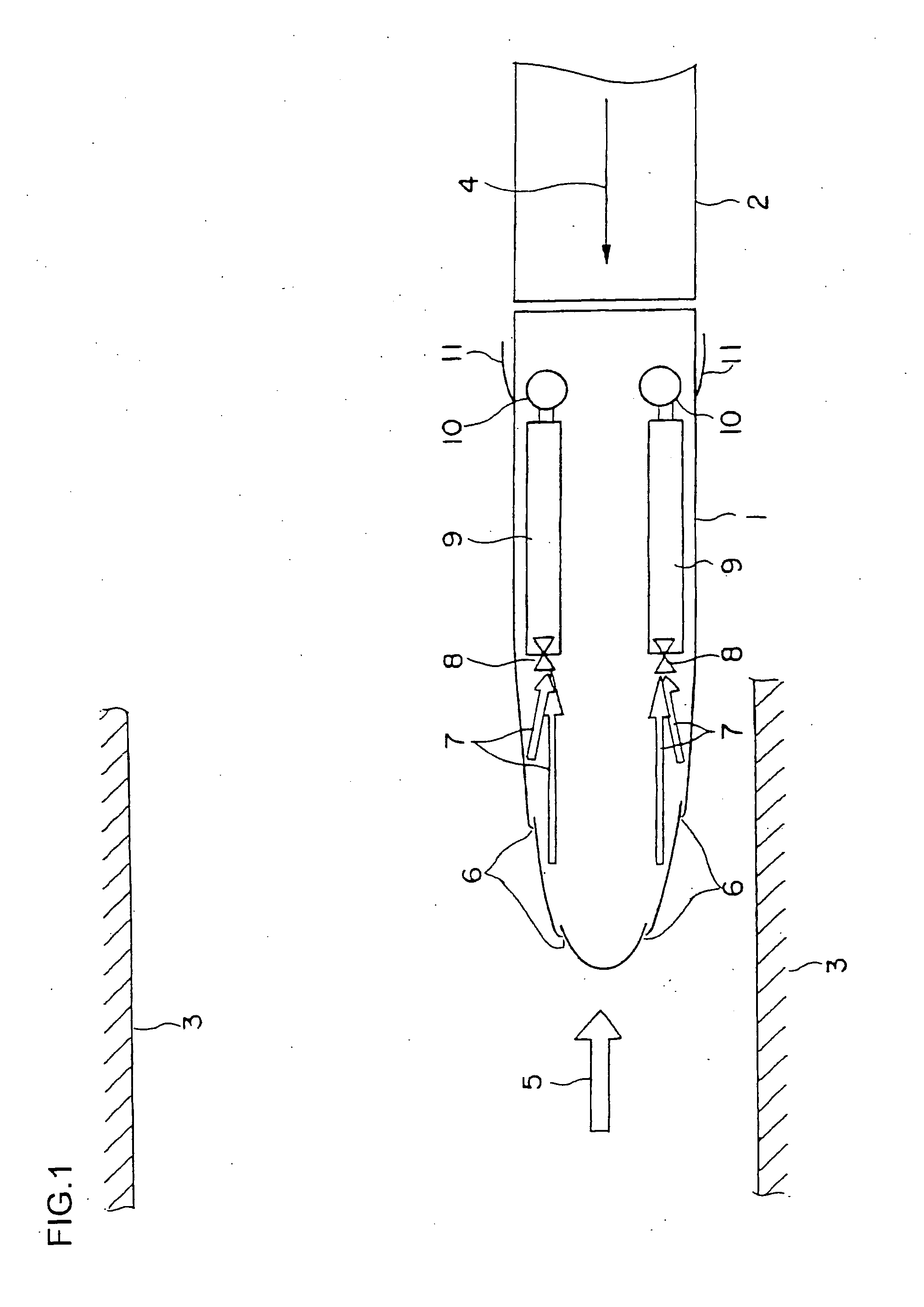
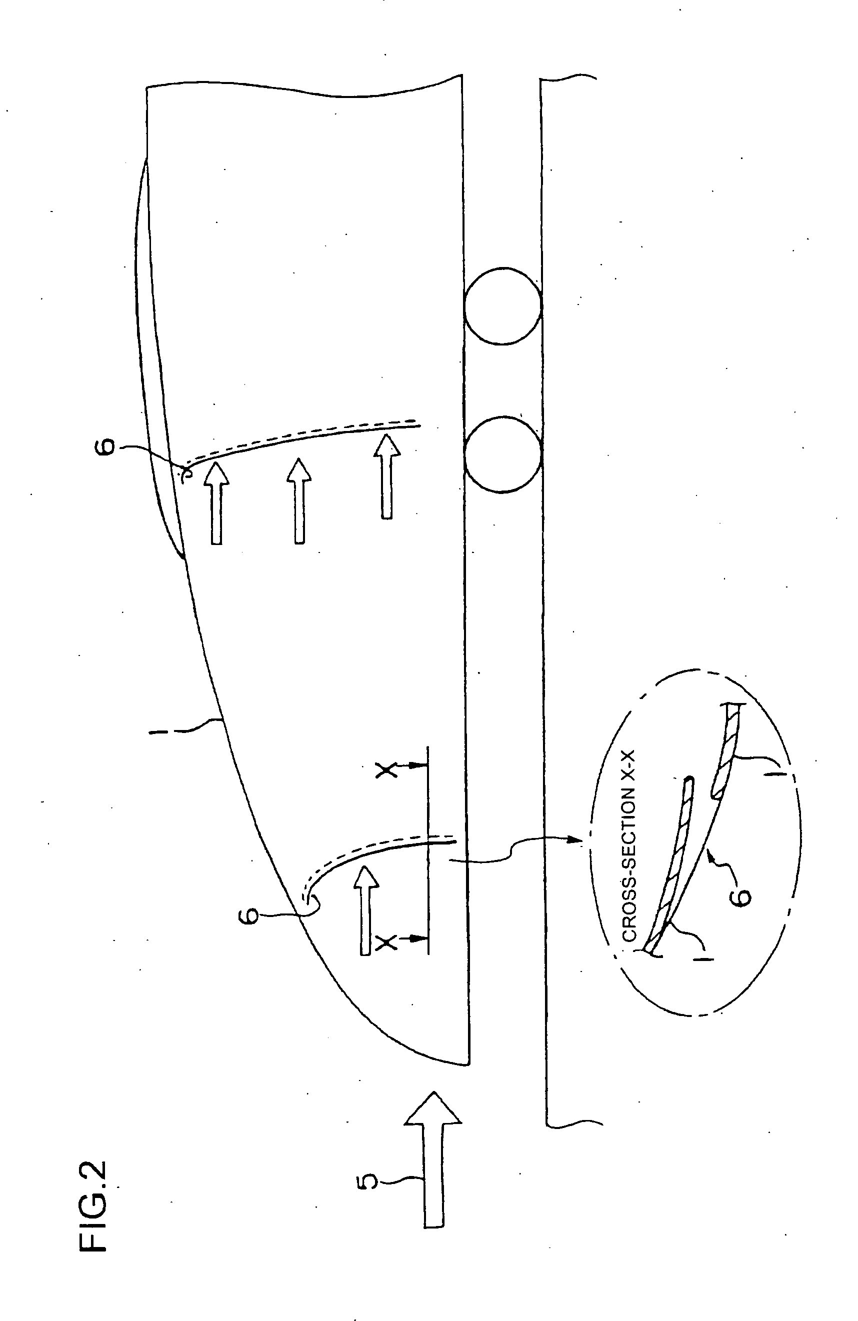
[0026]FIG. 1 is a plan view showing a portion of a vehicle formation including a leading vehicle according to embodiment 1 of the present invention, and FIG. 2 is an explanatory side view thereof. In FIG. 1, an intermediate vehicle 2 is connected to a leading vehicle 1. The vehicle formation composed of the leading vehicle 1, the intermediate vehicle(s) 2 and a leading vehicle 1 on the other end is about to enter a tunnel 3. Arrow 4 indicates the direction of travel of the vehicle. Arrow 5 indicates the direction of air flow that occurs relatively with respect to the traveling vehicle. An air inlet 6 for taking in air is formed on the surface of a nose portion of the leading vehicle 1. According to the present embodiment, air inlets 6 are disposed at two locations on both sides of the nose portion, respectively. Each of the air inlets 6 is respectively connected to an air flow path 7. In the drawing, the air flow paths 7 are shown by arrows. Reference number 9 denotes air reservoirs...

embodiment 2

[0037]FIG. 5 is an explanatory view showing in horizontal cross-section the car body according to embodiment 2 of the present invention. In embodiment 1, the air reservoirs (air intake tanks) are located in the leading vehicle 1, but there are cases where there may not be enough space for reservoirs in the leading vehicle 1 if the cross-sectional area of the nose portion of the leading vehicle 1 is reduced or if a space for forming the driver's seat must be reserved. In such a case, another set of air reservoirs (air intake tanks) 9 can be disposed on a intermediate vehicle 2 connected to the leading vehicle 1, that are directly communicated with the air reservoirs 9 on the leading vehicle 1. According to this arrangement, the amount of air intake can be increased, and the micropressure reduction performance can be enhanced.

embodiment 3

[0038]FIGS. 6 through 11 are referred to in describing another embodiment of a leading vehicle according to the present invention. FIG. 6 is a cross-sectional view of a nose portion of the leading vehicle, illustrating an air reservoir (air intake tank), a driver's cabin and an air inlet. FIG. 7 is a plan view of FIG. 6. FIG. 8 is a side view of the leading vehicle of the present embodiment, in which the nose portion is mainly illustrated. FIG. 9 is a birds-eye view of the nose portion of the leading vehicle. FIGS. 10 and 11 are graphs showing the result of analysis of the pressure change in the tunnel and the analyzed result of the micropressure waves when the leading vehicle enters the tunnel.

[0039] The leading vehicle 100 is equipped with an air reservoir (air intake tank) 110 and a driver's cabin 120 at the nose portion where the cross-sectional area is changed. The air reservoir 110 is disposed inside the cabin at the nose portion of the leading vehicle 100, and designed to ha...


PUM


Abstract

A railway vehicle comprises an air intake means 6 provided to a nose portion of a leading vehicle 1, an air tank (reservoir) 9 for storing intake air, and an air outlet 11, by which air is sucked in (breathed in) during entry of the leading vehicle to a tunnel and discharged within the tunnel, so as to reduce the pressure generated at the nose portion and to cut down micropressure waves. When the nose of the leading vehicle 1 enters a tunnel 3, an intake control valve 8 of the air reservoir depressurized to below atmospheric pressure (1 atm) opens to take in air through an air inlet 6 via a path 7 into the air reservoir 9. When the whole leading vehicle enters the tunnel, the intake control valve 8 closes, and air is discharged through the outlet 11 via a pump 10.

Description

[0001] The present application claims priority from Japanese patent application JP2003-430693 filed on Dec. 25, 2003, Japanese patent application JP2004-9647 filed on Jan. 16, 2004, and Japanese patent application JP2004-26301 filed on Feb. 3, 2004, the contents of which are hereby incorporated by reference into this application. FIELD OF THE INVENTION [0002] The present invention relates to a railway vehicle that runs on tracks having tunnels. DESCRIPTION OF THE RELATED ART [0003] Regarding the latest shinkansen trains (bullet trains), the maximum running speed is around 270 km / h to 300 km / h, and is determined to reach 350 km / h in the future. As the speed of the train increases, the shape of the car bodies and the flow of air are associated more closely with each other, and their influence on the environment is classified largely into the following two cases. [0004] The first is the case where the railway vehicle travels in a broad space such as when it runs in an environment refer...

Claims


Application Information

Patent Timeline
Patent Type & Authority Applications(United States)
IPC IPC(8): B61D17/02B61D27/00G10K11/16
CPCB61D17/02Y02T30/42Y02T30/32B61D27/0009Y02T30/00
Inventor HARADA, IWAOMATSUMOTO, MASAKAZU
Owner HITACHI LTD
Why Eureka
Try Eureka