Railway vehicle and method for operating vehicle
a technology for operating vehicles and railway vehicles, applied in locomotives, transportation and packaging, instruments, etc., can solve the problems of reducing the maximum number of passengers on the railway vehicle, reducing the cabin space, and serious environmental problems, and achieve the effect of reducing the micropressure wav
- Summary
- Abstract
- Description
- Claims
- Application Information
AI Technical Summary
Benefits of technology
Problems solved by technology
Method used
Image
Examples
embodiment 1
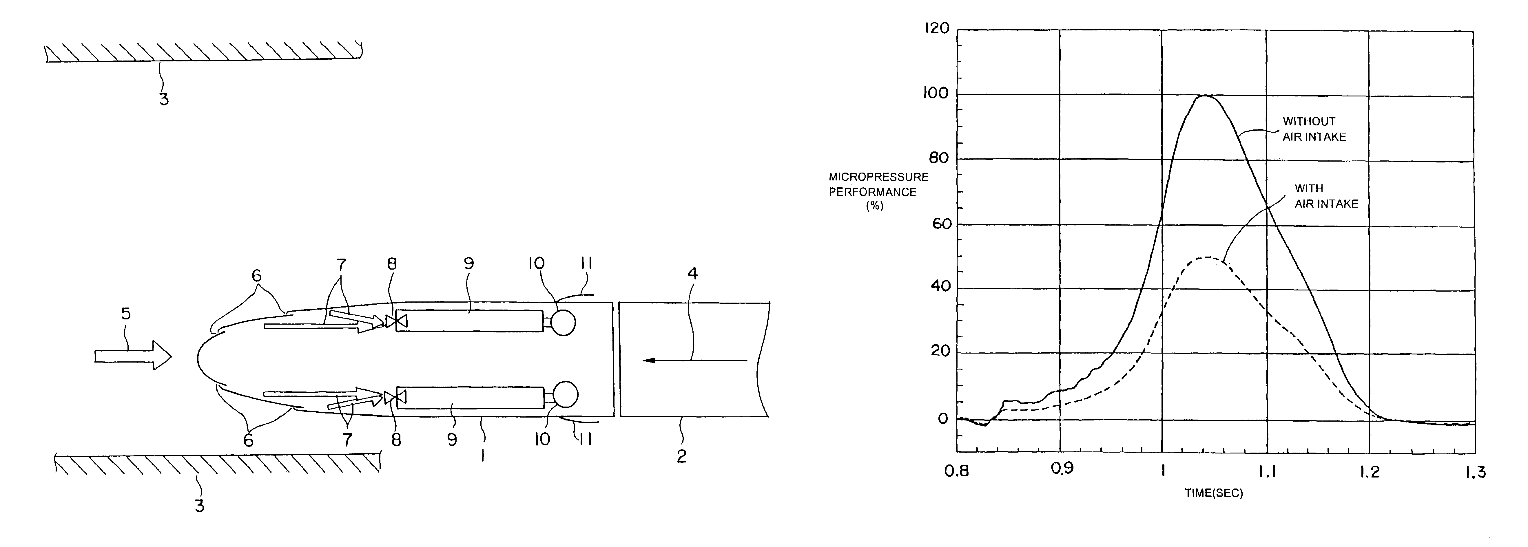
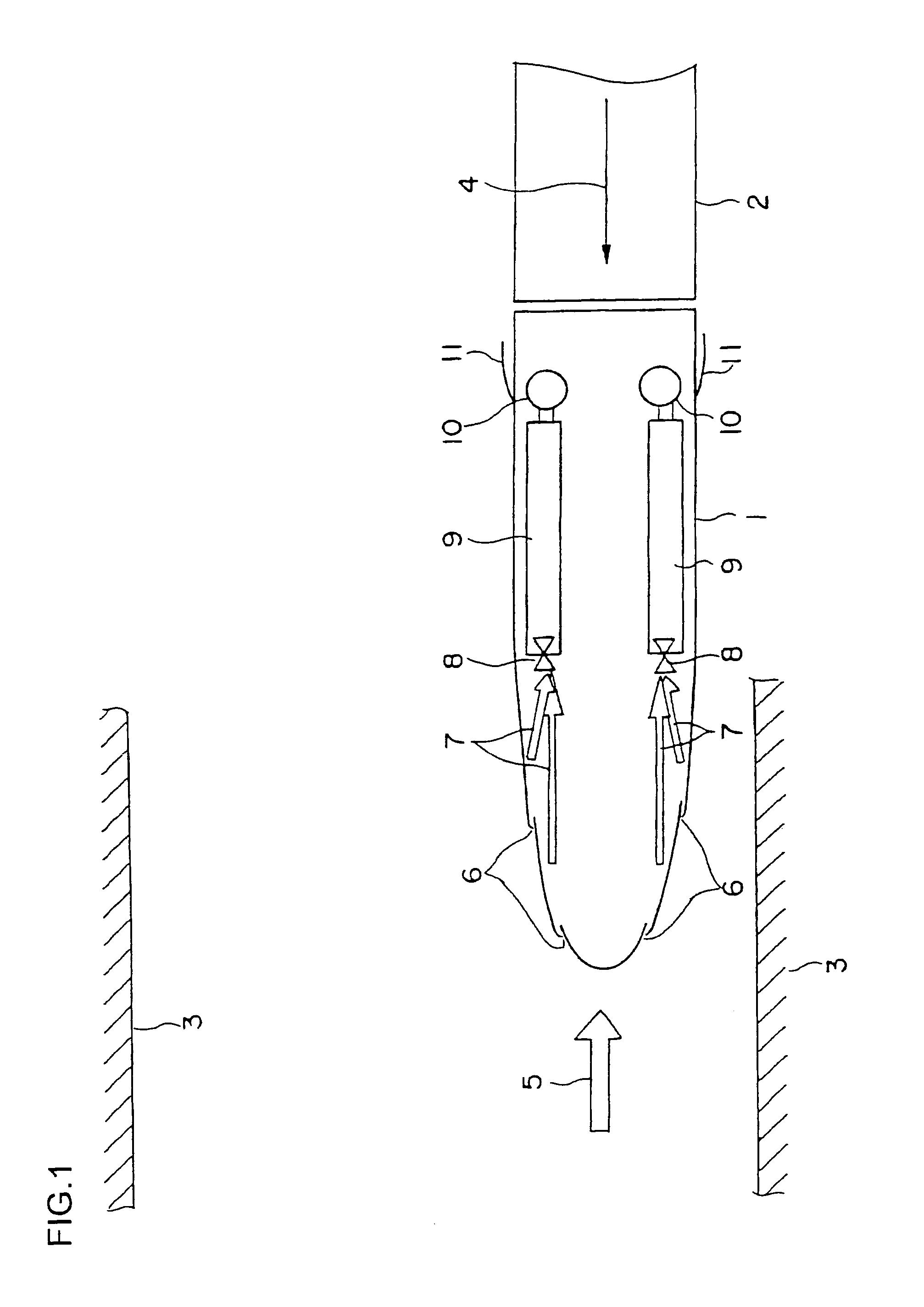
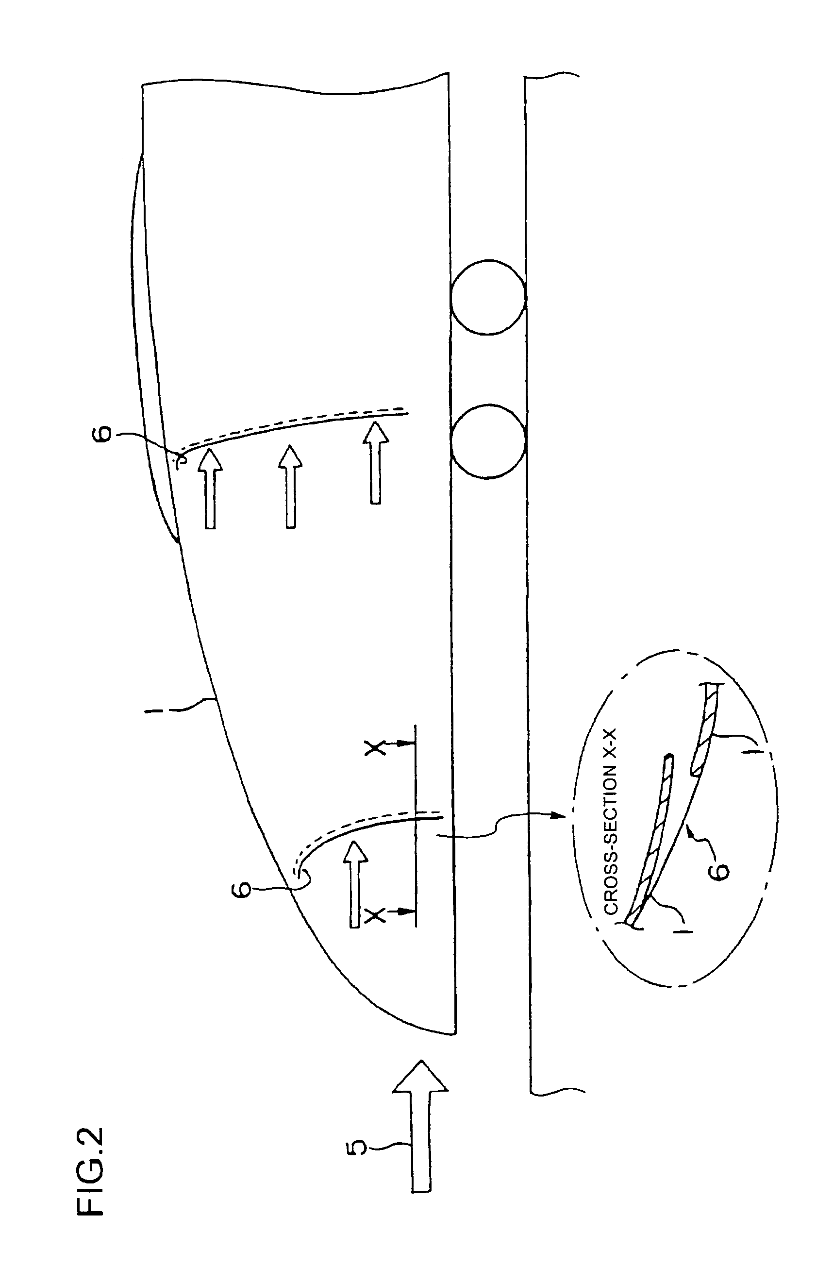
[0025]FIG. 1 is a plan view showing a portion of a vehicle formation including a leading vehicle according to embodiment 1 of the present invention, and FIG. 2 is an explanatory side view thereof. In FIG. 1, an intermediate vehicle 2 is connected to a leading vehicle 1. The vehicle formation composed of the leading vehicle 1, the intermediate vehicle(s) 2 and a leading vehicle 1 on the other end is about to enter a tunnel 3. Arrow 4 indicates the direction of travel of the vehicle. Arrow 5 indicates the direction of air flow that occurs relatively with respect to the traveling vehicle. An air inlet 6 for taking in air is formed on the surface of a nose portion of the leading vehicle 1. According to the present embodiment, air inlets 6 are disposed at two locations on both sides of the nose portion, respectively. Each of the air inlets 6 is respectively connected to an air flow path 7. In the drawing, the air flow paths 7 are shown by arrows. Reference number 9 denotes air reservoirs...
embodiment 2
[0036]FIG. 5 is an explanatory view showing in horizontal cross-section the car body according to embodiment 2 of the present invention. In embodiment 1, the air reservoirs (air intake tanks) are located in the leading vehicle 1, but there are cases where there may not be enough space for reservoirs in the leading vehicle 1 if the cross-sectional area of the nose portion of the leading vehicle 1 is reduced or if a space for forming the driver's seat must be reserved. In such a case, another set of air reservoirs (air intake tanks) 9 can be disposed on a intermediate vehicle 2 connected to the leading vehicle 1, that are directly communicated with the air reservoirs 9 on the leading vehicle 1. According to this arrangement, the amount of air intake can be increased, and the micropressure reduction performance can be enhanced.
embodiment 3
[0037]FIGS. 6 through 11 are referred to in describing another embodiment of a leading vehicle according to the present invention. FIG. 6 is a cross-sectional view of a nose portion of the leading vehicle, illustrating an air reservoir (air intake tank), a driver's cabin and an air inlet. FIG. 7 is a plan view of FIG. 6. FIG. 8 is a side view of the leading vehicle of the present embodiment, in which the nose portion is mainly illustrated. FIG. 9 is a birds-eye view of the nose portion of the leading vehicle. FIGS. 10 and 11 are graphs showing the result of analysis of the pressure change in the tunnel and the analyzed result of the micropressure waves when the leading vehicle enters the tunnel.
[0038]The leading vehicle 100 is equipped with an air reservoir (air intake tank) 110 and a driver's cabin 120 at the nose portion where the cross-sectional area is changed. The air reservoir 110 is disposed inside the cabin at the nose portion of the leading vehicle 100, and designed to have...
PUM
 Abstract
Description
Claims
Application Information
 - R&D
- Intellectual Property
- Life Sciences
- Materials
- Tech Scout
- Unparalleled Data Quality
- Higher Quality Content
- 60% Fewer Hallucinations
Browse by: Latest US Patents, China's latest patents, Technical Efficacy Thesaurus, Application Domain, Technology Topic, Popular Technical Reports.
© 2025 PatSnap. All rights reserved.Legal|Privacy policy|Modern Slavery Act Transparency Statement|Sitemap|About US| Contact US: help@patsnap.com


