Test strip qualification system

a test strip and strip technology, applied in the field of test strip qualification system, can solve the problems of failing control, erroneously concluding that a proper sample is needed,

Inactive Publication Date: 2005-07-14
LIFESCAN INC
View PDF17 Cites 21 Cited by
  • Summary
  • Abstract
  • Description
  • Claims
  • Application Information

AI Technical Summary

Problems solved by technology

However, that simple system cannot easily distinguish between a whole blood sample and some other liquid (e.g. blood serum) placed in the sample port in error or, even, an object (e.g., a finger) that can approach sample port 10 and cause the system to erroneously conclude that a proper sample has been applied.
Ageing or oxidization of reagents can potentially yield failing Control 1 an / or Control 2 tests.

Method used


Image

  • Test strip qualification system
  • Test strip qualification system
  • Test strip qualification system

Examples


examples

[0033] A series of trials were conducted in connection with the present invention as early as March 2000. These trials were of an experimental nature, necessary to determine and / or verify the accuracy of the test strip qualification approach taught herein. The results of such testing gave positive indication of sufficient accuracy in test strip accuracy achieved through use of the present inventions. As of the filing date for this Specification, no product according to the present invention has yet been made available to the public.

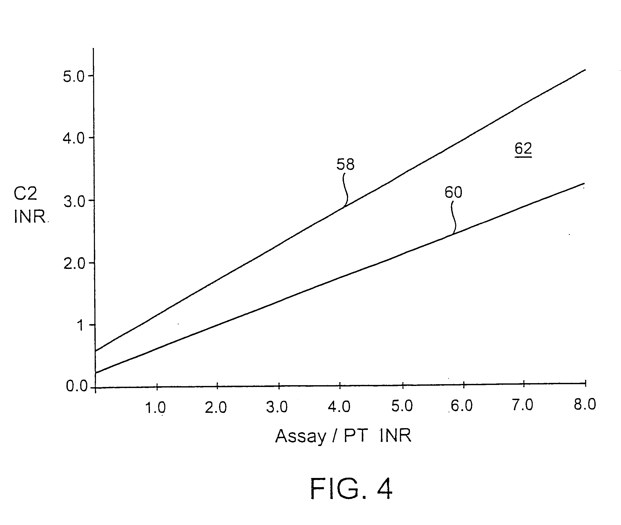
[0034] The accuracy of the inventive methods function was first studied in connection with subjects enrolled at three independent institutions for evaluation against test strips as described above. In such clinical trials, venous blood was drawn and tested on a reference clinical laboratory device. These results were used for absolute reference. By comparison through expanded agreement analysis, which considers comparison of the clinical interpretation o...


PUM

PropertyMeasurementUnit
temperatureaaaaaaaaaa
timeaaaaaaaaaa
areaaaaaaaaaaa

Abstract

In connection with a fluidic medical diagnostic device that permits measurement of the coagulation time of blood, software, methods and associated devices for quality control are disclosed. The fluidic device preferably comprises a test strip with one end having a sample port for introducing a sample and a bladder at the other end for drawing the sample to a measurement area. A channel carries sample from the sample port to an assay measurement area and first and second control measurement areas. Preferably a stop junction, between the measurement areas and bladder, halts the sample flow for measurement. If results from measurements taken for each control fall within a predetermined zone or defined limits, the assay measurement is qualified. If not, an error is registered and the test strip is counted as unfit.

Description

FIELD OF THE INVENTION [0001] This invention relates to approaches for qualifying results obtained in using analyte test strips. The invention is particularly suited for testing the quality of test strips used for measuring prothrombin time (PT time) with whole blood in which a measurement area includes a composition that catalyzes the blood clotting cascade. BRIEF DESCRIPTION OF THE DRAWINGS [0002]FIGS. 1-3 represent information known in the art and are referenced in the Background of the Invention. Each of FIGS. 4A-5B diagrammatically illustrates aspects of the present invention. Variation of the invention from that shown in the figures is contemplated. [0003]FIG. 1A is a top view of a test strip as may be used in connection with the present invention; FIG. 1B is a side view of the test strip. [0004]FIG. 2A is a schematic of hardware elements for a meter for that may be used in the present invention; FIG. 2B shows an alternative variation of an element of the meter of FIG. 2A. [00...

Claims


Application Information

Patent Timeline
Patent Type & Authority Applications(United States)
IPC IPC(8): G01N33/86G01N33/49G01N33/558
CPCG01N33/558Y10T436/2575Y10T436/10G01N33/52G01N33/4905
Inventor PATEL, HARSHADWITT, JAMES
Owner LIFESCAN INC
Why Eureka
Try Eureka