Tool

a tool and tool body technology, applied in the field of tools, can solve the problems of not being suitable for tools of the above type, requiring very accurate implementation, and regularly difficult supporting parts, and achieve the effect of easy and rapid implementation of the connection between the supporting part and the working par

Inactive Publication Date: 2005-07-14
FA AUGUST RUGGEBRERG
View PDF9 Cites 34 Cited by
  • Summary
  • Abstract
  • Description
  • Claims
  • Application Information

AI Technical Summary

Benefits of technology

[0006] It is an object of the invention to embody a tool of the generic type in such a way that producing and rel

Problems solved by technology

Attaching the working part to, and detaching it from, the supporting part is regularly rather difficult or needs very accurate implementation, which is in parti

Method used


Image

  • Tool
  • Tool
  • Tool

Examples


Embodiment Construction

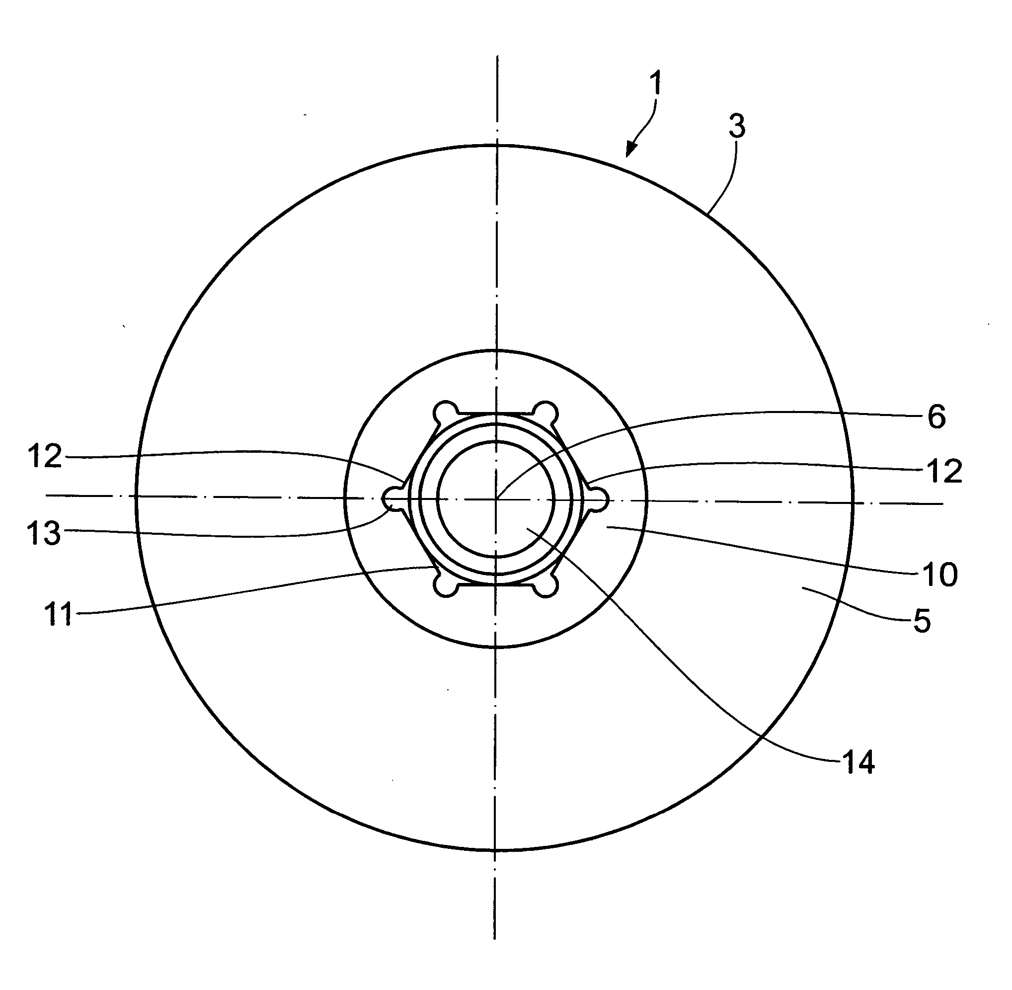
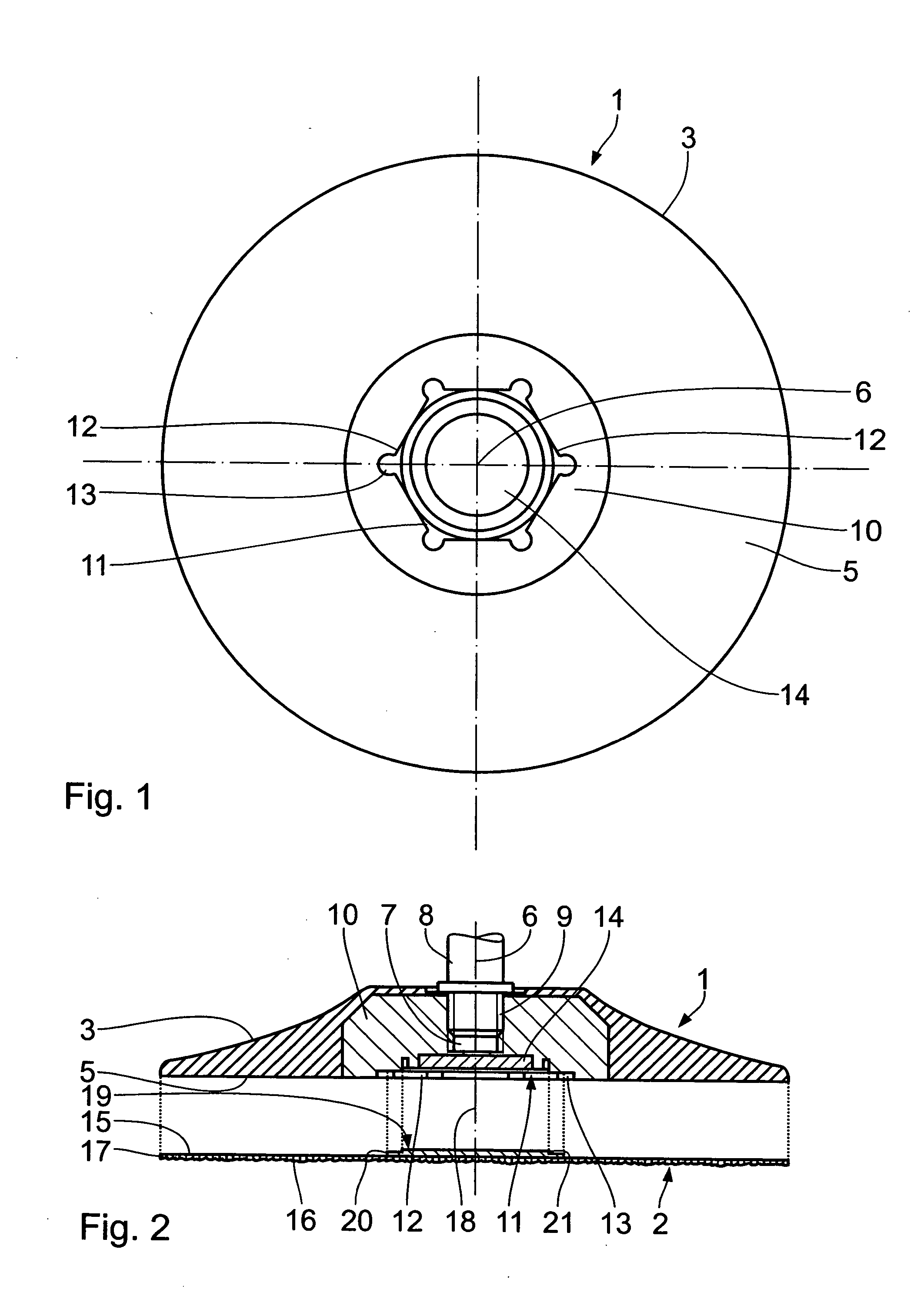
[0018] As seen in the drawing, the tool in its fundamental structure comprises a supporting part 1 in the form of a supporting plate, and a working part 2. The supporting part 1 has a supporting casing 3 of flexible plastics which includes an annular supporting face 5. On the side turned away from the supporting face 5, the supporting part 1 comprises a threaded hole 7 which is concentric of the center line 6 and into which to insert a drive shaft 8 of a tool-actuating unit (not shown) by a corresponding external thread 9. These kinds of tool drive units can be so-called right angle grinders or spur wheel grinders.

[0019] In the supporting casing 3 on the side of the supporting face 5, provision is made for a retainer 10 which includes the threaded hole 7 and, concentrically of the center line 6, a flat recess 11 of polygonal cross-sectional shape. In the present case, the recess 11 is formed by flanks 12 of an equilateral and equiangular polygon, for example a hexagon. A cutout 13 ...


PUM


Abstract

In a tool comprising a supporting part and a disk-shaped working part for machining operation, the supporting part comprises a supporting face for the working part and a permanent magnet within the supporting face. The working part comprises a coupling member of ferromagnetic material which is movable into magnetically clinging connection with the permanent magnet upon application of a counterpart supporting face to the supporting face.

Description

BACKGROUND OF THE INVENTION [0001] 1. Field of the Invention [0002] The invention relates to a tool comprising a supporting part and a disk-shaped working part for machining operation. [0003] 2. Background Art [0004] Tools of the generic type come in the most various designs, having a supporting part or base member that is joined to a working part which is a wearing part. These working parts are for instance abrasives on a backing, polishing wheels, cleaning wheels which consist of abrasive embedded in needled nonwoven or felt wheels. The supporting part and the working part are regularly driven in rotation. In known designs, a coupling member is mounted on the side that faces away from the working side, having a female thread that is screwed on a thread of the supporting part. Attaching the working part to, and detaching it from, the supporting part is regularly rather difficult or needs very accurate implementation, which is in particular stressed by the fact that these working pa...

Claims


Application Information

Patent Timeline
IPC IPC(8): B24B45/00B24D9/00
CPCB24D9/006B24B45/006
Inventor STEIN, MARKUSHUTH, NICOLAS
Owner FA AUGUST RUGGEBRERG
Why Eureka
Try Eureka