Gas turbine engine

a technology of gas turbine engine and turbine engine, which is applied in the direction of liquid fuel engine, machine/engine, efficient propulsion technology, etc., can solve the problems of deteriorating energy efficiency of jet engine and increased flow rate of cooling air to generate energy loss

Inactive Publication Date: 2005-07-28
IHI CORP
View PDF5 Cites 10 Cited by
  • Summary
  • Abstract
  • Description
  • Claims
  • Application Information

AI Technical Summary

Benefits of technology

[0010] It is a second object of the invention to provide a gas turbine engine capable of sufficiently preventing the comb

Problems solved by technology

On the other hand, the turbine disc is sufficiently cooled, however, the consumed flow rate of the cooli

Method used


Image

  • Gas turbine engine
  • Gas turbine engine
  • Gas turbine engine

Examples


Embodiment Construction

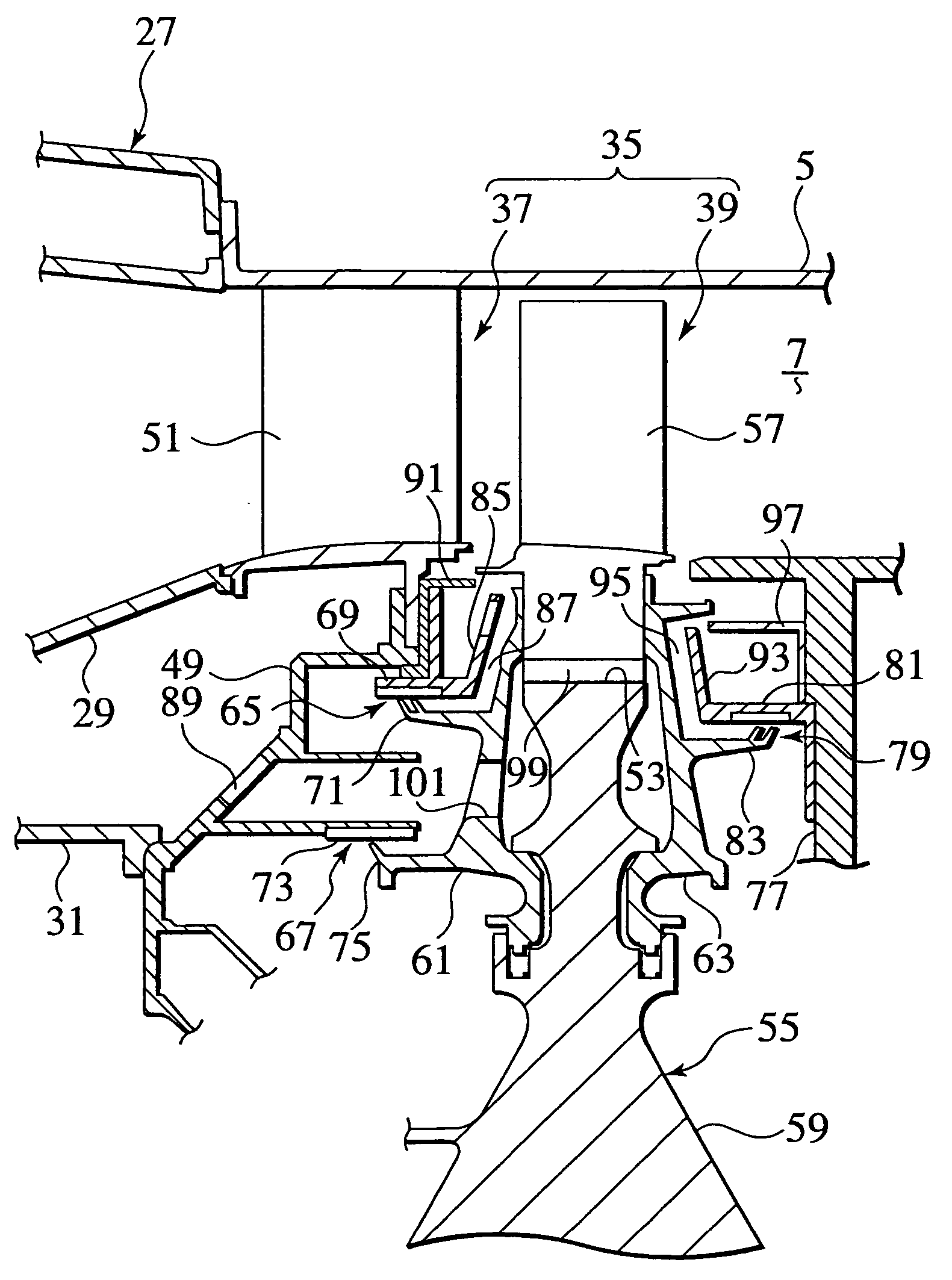
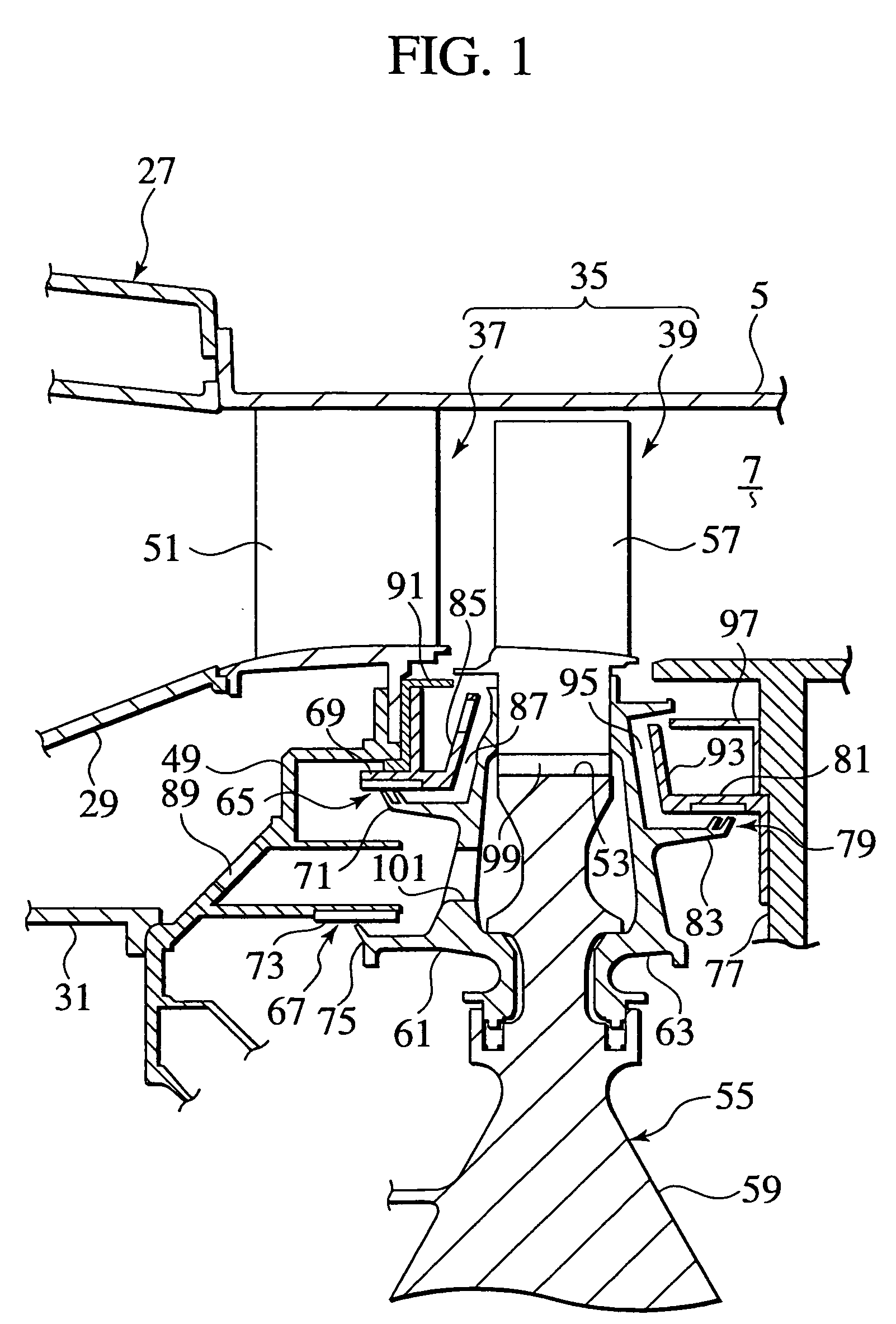
[0039] Referring now to FIGS. 1 and 2, an embodiment of the present invention will be explained hereinbelow.

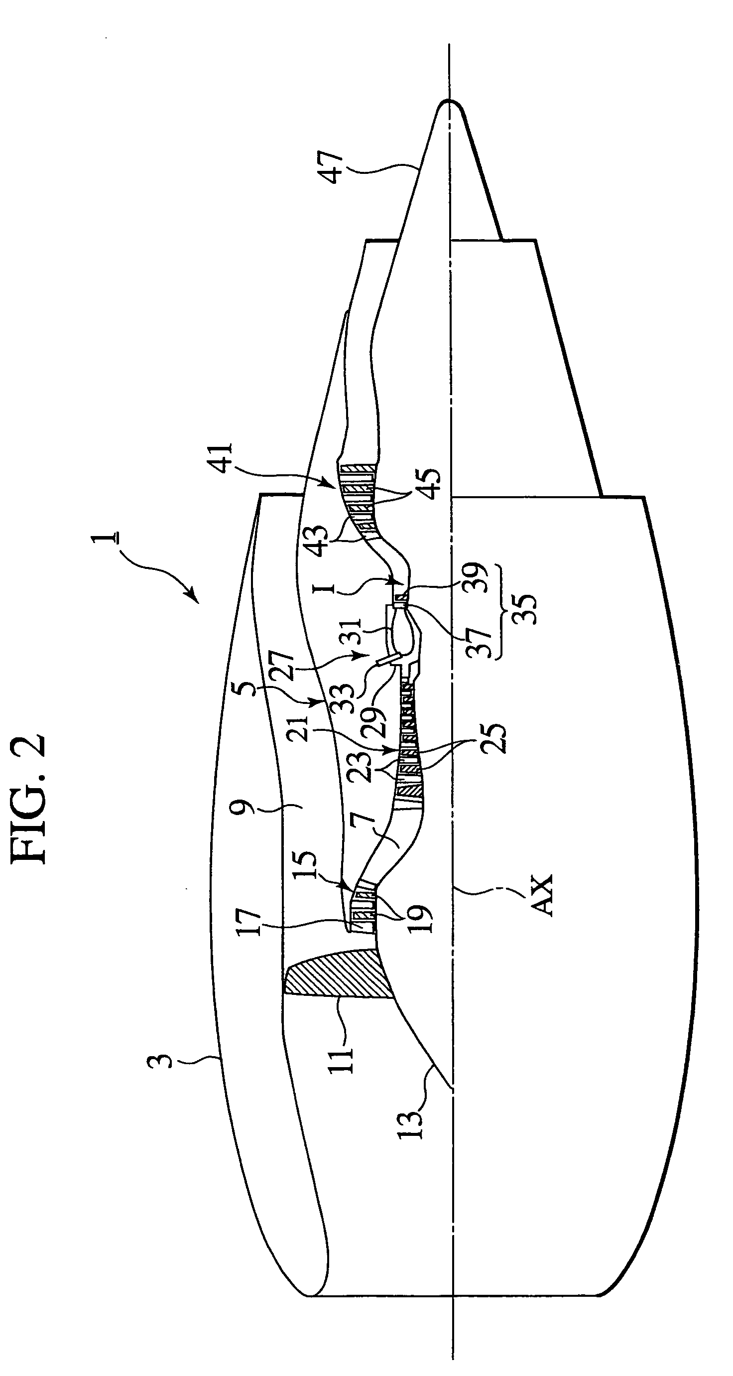
[0040]FIG. 1 is an enlarged view of a portion I shown with an arrow in FIG. 2, and FIG. 2 is a schematic partially sectional view of a jet engine according to the embodiment of the present invention. Here, the term “front” means “left” in FIGS. 1 and 2, and the term “rear” means “right” in FIGS. 1 and 2.

[0041] As shown in FIG. 2, the jet engine (one of gas turbine engines) 1 according to the embodiment of the present invention is used for an aircraft. The jet engine mainly comprises an outer cylinder frame 3 and an inner cylinder frame 5 which is integrally provided inside the outer cylinder frame 3. An annular main passage (core passage) 7 is formed inside the inner cylinder frame 5. An inner bypass passage 9 is formed between an inner side of the outer cylinder frame 3 and an outer side of the inner cylinder frame 5.

[0042] A fan 11 is rotatably provided on a front end of ...


PUM


Abstract

A gas turbine engine includes a front cooling plate (85) provided on a front stationary section (69) in the vicinity of a front side of a turbine disc (55), a front cooling passage (87) formed between an opposing surface of the front cooling plate (85) and a front surface of a rim of the turbine disc (55), a rear cooling plate (93) provided on a rear stationary section (81) in the vicinity of a rear side of the turbine disc (55), and a rear cooling passage (95) formed between an opposing surface of the rear cooling plate (93) and a rear surface of the rim of the turbine disc (55).

Description

TECHNICAL FIELD [0001] The present invention relates to a gas turbine engine such as a jet engine capable of obtaining rotation force from a turbine by operating the turbine by means of expansion of a combustion gas or capable of obtaining propulsion by injecting combustion gas injected from the turbine. BACKGROUND ART [0002] Japanese Patent Application Laid-open No. Hei8-296455 (laid open in 1996) discloses a conventional technique of a jet engine as one example of conventional gas turbine engines. This conventional technique will be briefly explained hereinbelow. [0003] The jet engine includes a fan which takes in air, a compressor which compresses the air taken by the fan, a combustor which burns fuel in the compressed air compressed by the compressor, and a turbine which is operated by expansion of combustion gas from the combustor and which operates the fan and the compressor in association. [0004] Thus, air is taken in by the operation of the fan, and the air is compressed by ...

Claims


Application Information

Patent Timeline
IPC IPC(8): F02C7/18F01D5/08F01D11/02F02C7/28
CPCF01D5/082Y02T50/676F02C7/28F01D11/02F01D5/3015F01D11/001Y02T50/60F02C7/18
Inventor OKITA, YOJIYAMAWAKI, SHIGEMICHI
Owner IHI CORP
Why Eureka
Try Eureka