Check patentability & draft patents in minutes with Patsnap Eureka AI!

Wiper blade and wiper system having the same

a technology of wiper blade and wiper blade, which is applied in the field of wiper blade, can solve the problems of increasing the size of each lever, disadvantageous increase of the wall thickness of each lever, and generally poor appearance of the wiper blade, so as to achieve the effect of enabling the flexing of the wiper strip

Active Publication Date: 2005-08-04
DENSO CORP
View PDF8 Cites 76 Cited by
  • Summary
  • Abstract
  • Description
  • Claims
  • Application Information

AI Technical Summary

Benefits of technology

[0012] The present invention addresses the above disadvantages. Thus, it is an objective of the present invention to provide a wiper blade, which includes a cover member that has a structure enabling flexing of a wiper strip. It is another objective of the preset invention to provide a wiper blade, which effectively limits lifting of the wiper blade from a wiping surface at time of traveling of a vehicle. It is another objective of the present invention to provide a vehicle wiper system, which includes one of the above wiper blades.

Problems solved by technology

However, such a wiper blade generally does not have good appearance due to exposure of the lever assembly, which includes the metal levers.
However, in the lever assembly disclosed in the above publication, each lever is made of the resin, so that a wall thickness of each lever needs to be disadvantageously increased to achieve a required strength and a required rigidity.
This results in an increase in the size of each lever and also an increase in the size of the lever assembly.
Thus, the wiper blade disadvantageously becomes larger than the wiper blade having the metal levers.
However, the ends of the wiper strip are significantly flexed during its wiping operation due to a change in the curvature of the wiping surface of the glass.
Thus, depending on the installation position of the fin member, the fin member may cause an increase in the size of the wiper blade in a transverse direction or in a vertical direction.
Furthermore, the lever assembly is directly exposed and is not made integrally with the fin member.
Thus, appearance of the wiper blade is not good.

Method used


Image

  • Wiper blade and wiper system having the same
  • Wiper blade and wiper system having the same
  • Wiper blade and wiper system having the same

Examples


first embodiment

[0085] A first embodiment of the present invention will be described with reference to the accompanying drawings. In the following respective drawings, some lines on a lateral side surface of the wiper strip 5 are eliminated for the sake of clarity.

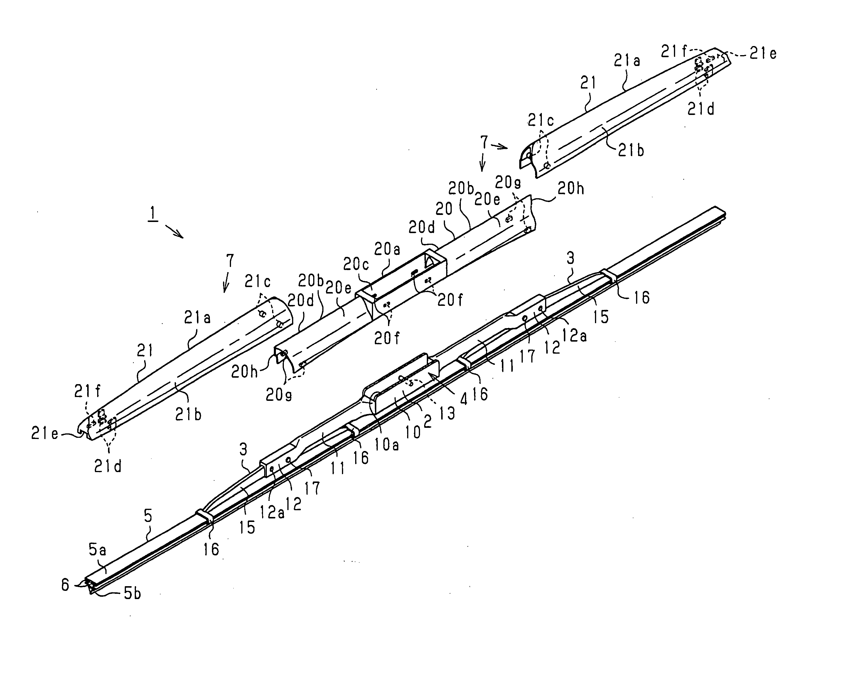
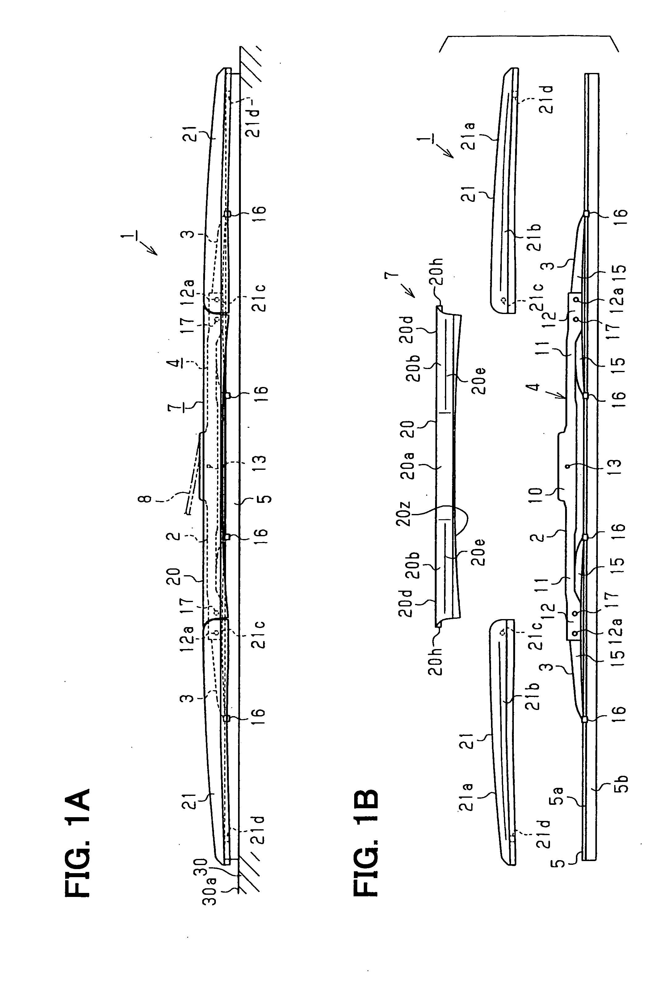
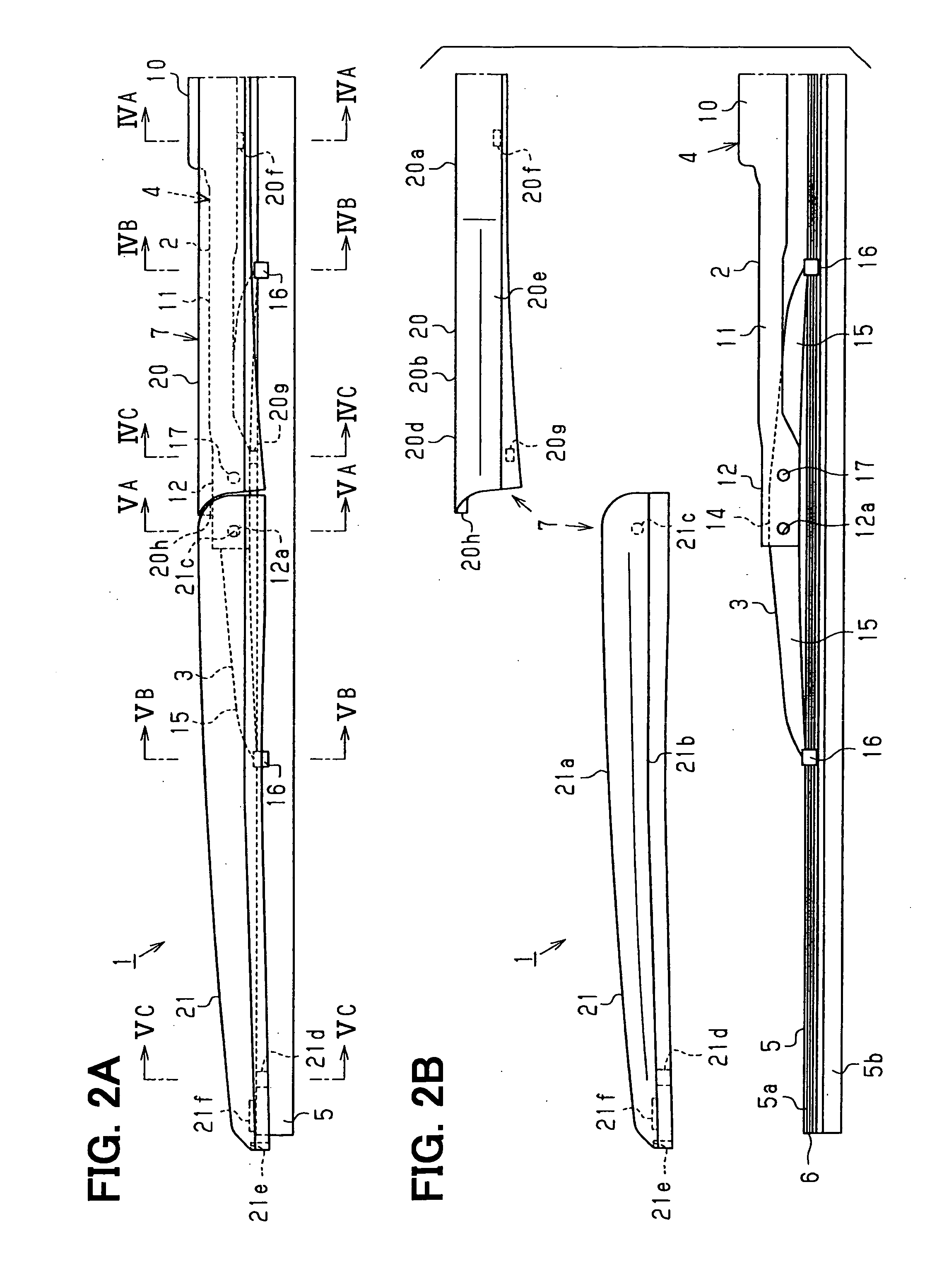
[0086]FIG. 1A shows a wiper blade 1 of a wiper system of the present embodiment, which is used to wipe a front glass (a windshield) 30 of a vehicle. The wiper blade 1 is connected to a distal end of a wiper arm 8 and receives an urging force from the wiper arm 8 against a glass surface 30a of the front glass 30. The wiper arm 8 is reciprocally rotated a predetermined angle by a wiper motor (not shown), so that the wiper blade 1 reciprocally wipes a predetermined angular range of the glass surface (a wiping surface) 30a of the front glass 30a. As shown in FIGS. 1A to 3, the wiper blade 1 includes a lever assembly 4, a wiper strip 5, two backing plates 6 and a cover member (a fin member) 7. The lever assembly 4 includes a primary lever 2 a...

second embodiment

[0119] A second embodiment of the present invention will be described with reference to the accompanying drawings.

[0120] The wiper blade 1 of the present embodiment differs from the wiper blade 1 of the first embodiment mainly in the structure of the cover member 7. Thus, in the following description, the cover member 7 will be mainly described, and the components similar to those of the first embodiment will be indicated by the same numerals and will not be described further.

[0121] As shown in FIGS. 7A to 9, the cover member 7 includes the center cover portion 20 and the two side cover portions 21. The side cover portions 21 are located at opposed ends, respectively, of the center cover portion 20. Each of the center cover portion 20 and the side cover portions 21 is made of the synthetic resin material and has a predetermined rigidity. The center cover portion 20 and the side cover portions 21 receive and cover the lever assembly 4 in such a manner that the center cover portion ...

third embodiment

[0130] A third embodiment of the present invention will be described with reference to the accompanying drawings.

[0131] The wiper blade 1 of the present embodiment differs from the wiper blade 2 of the second embodiment mainly in the structure of the cover member 7. Thus, in the following description, the cover member 7 will be mainly described, and the components similar to those of the first and second embodiments will be indicated by the same numerals and will not be described further.

[0132] As shown in FIGS. 10A to 12, the cover member 7 includes the center cover portion 20, the side cover portion 21 and a side cover portion 22, which are made of the synthetic resin and have the predetermined rigidity. The side cover portion 21 is located on the one side of the center cover portion 20, and the side cover portion 22 is located on the other side of the center cover portion 20. That is, the wiper blade 1 of the present embodiment has the side cover portion 21 of the second embodi...


PUM


Abstract

A lever assembly holds a wiper strip, which directly wipes a wiping surface. The lever assembly includes a plurality of levers, which are connected together in tournament style. An axial length of the lever assembly is shorter than an axial length of the wiper strip. A cover member receives the lever assembly, and opposed ends of the cover member hold the wiper strip. The cover member includes a plurality of cover portions, which are formed separately from one another.

Description

CROSS REFERENCE TO RELATED APPLICATION [0001] This application is based on and incorporates herein by reference Japanese Patent Application No. 2004-24787 filed on Jan. 30, 2004, Japanese Patent Application No. 2004-78948 filed on Mar. 18, 2004, Japanese Patent Application No. 2004-85417 filed on Mar. 23, 2004, Japanese Patent Application No. 2004-158106 filed on May 27, 2004, Japanese Patent Application No. 2004-214769 filed on Jul. 22, 2004, Japanese Patent Application No. 2004-239845 filed on Aug. 19, 2004 and Japanese Patent Application No. 2004-239848 filed on Aug. 19, 2004. BACKGROUND OF THE INVENTION [0002] 1. Field of the Invention [0003] The present invention relates to a wiper blade, which includes a lever assembly made by connecting levers in tournament style, and more particularly to a wiper blade suitable for wiping a surface of a vehicle front glass (a windshield), which shows a large change in a curvature of the surface. The present invention further relates to a vehi...

Claims


Application Information

Patent Timeline
IPC IPC(8): B60S1/38
CPCB60S1/3806
Inventor NAKANO, HIROYUKITORII, NAOKISAITO, TOSHIHIROTAKAGI, ATSUSHIYANO, MOTOYASUMATSUMOTO, HIROSHIKOBAYASHI, YUKIOHIROTA, YOSHITO
Owner DENSO CORP
Features
  • R&D
  • Intellectual Property
  • Life Sciences
  • Materials
  • Tech Scout
  • Unparalleled Data Quality
  • Higher Quality Content
  • 60% Fewer Hallucinations
Learn More