Mechanically sealed adjustable gas nozzle

Inactive Publication Date: 2005-08-04
BURNER SYST INT
View PDF6 Cites 50 Cited by
  • Summary
  • Abstract
  • Description
  • Claims
  • Application Information

AI Technical Summary

Benefits of technology

[0005] It is a further object of the present invention to provide an adjustable gas nozzle having a flow adjusting member positioned within a nozzle body supported on a conduit about which the nozzle body is threadably received, the adjusting member being moveable alternatively into or out of engagement with an interior wall of the nozzle body and having a configuration that permits gas to flow within a hollow therein and to the outlet orifice of the nozzle body at a first flow rate when it is in engagement with the interior of the nozzle body and to provide a flow path about the adjusting member for the gas to flow thereby to provide additional gas to flow through the outlet orifice of the nozzle body when out of engagement with the interior of the nozzle body.

Problems solved by technology

These seals under the high temperature conditions in a self-cleaning oven cycle may be subject to problems such as heretofore described.

Method used


Image

  • Mechanically sealed adjustable gas nozzle
  • Mechanically sealed adjustable gas nozzle
  • Mechanically sealed adjustable gas nozzle

Examples


Embodiment Construction

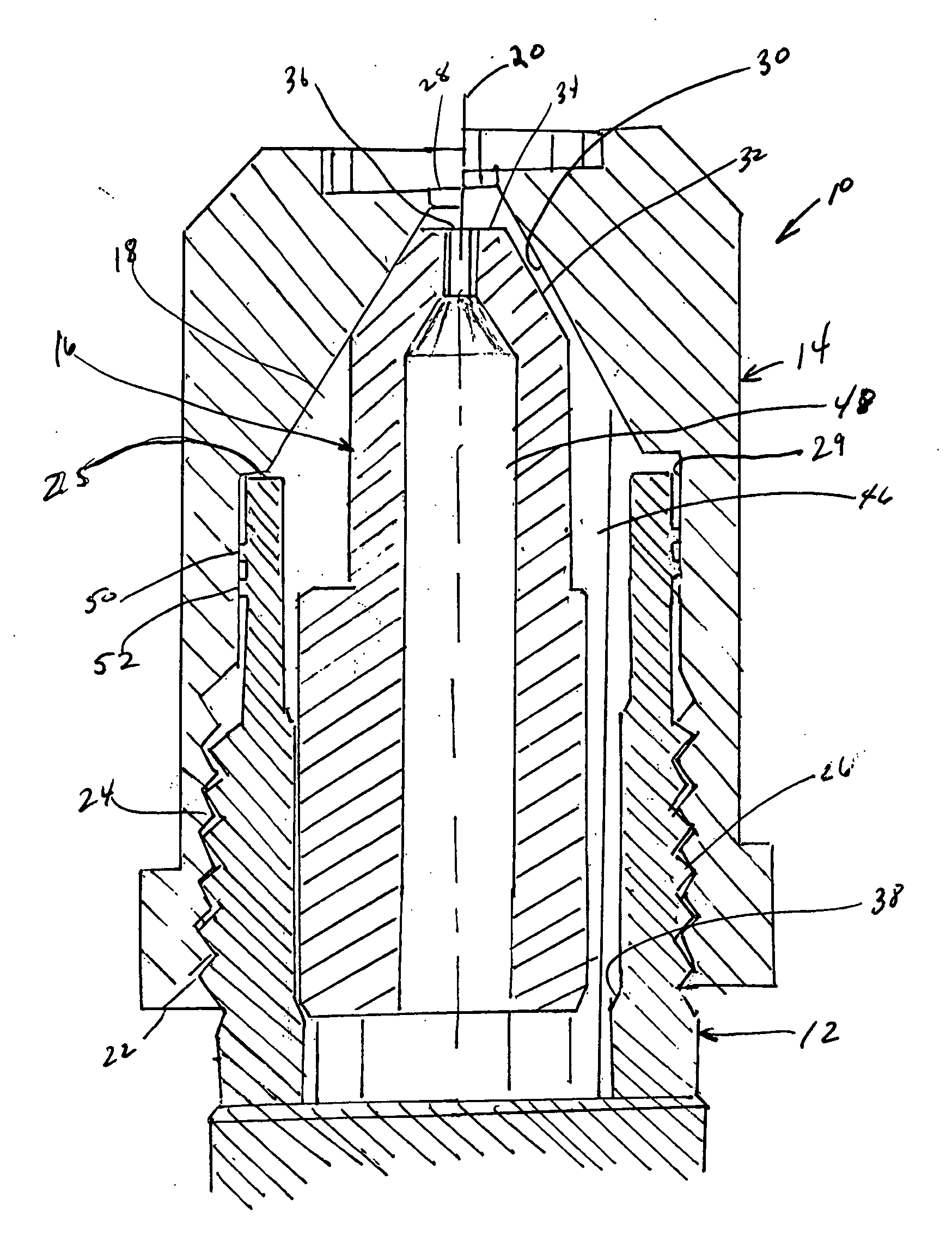
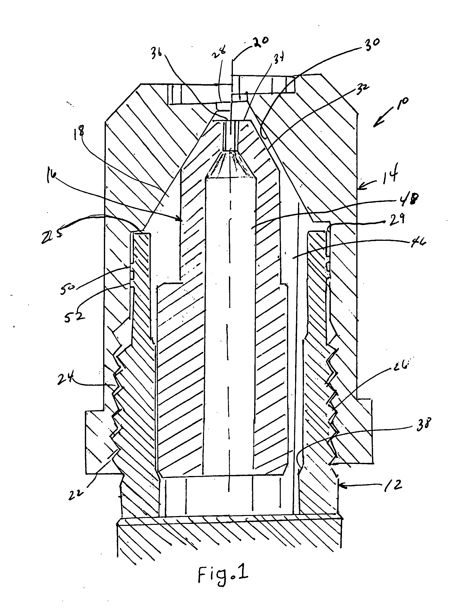
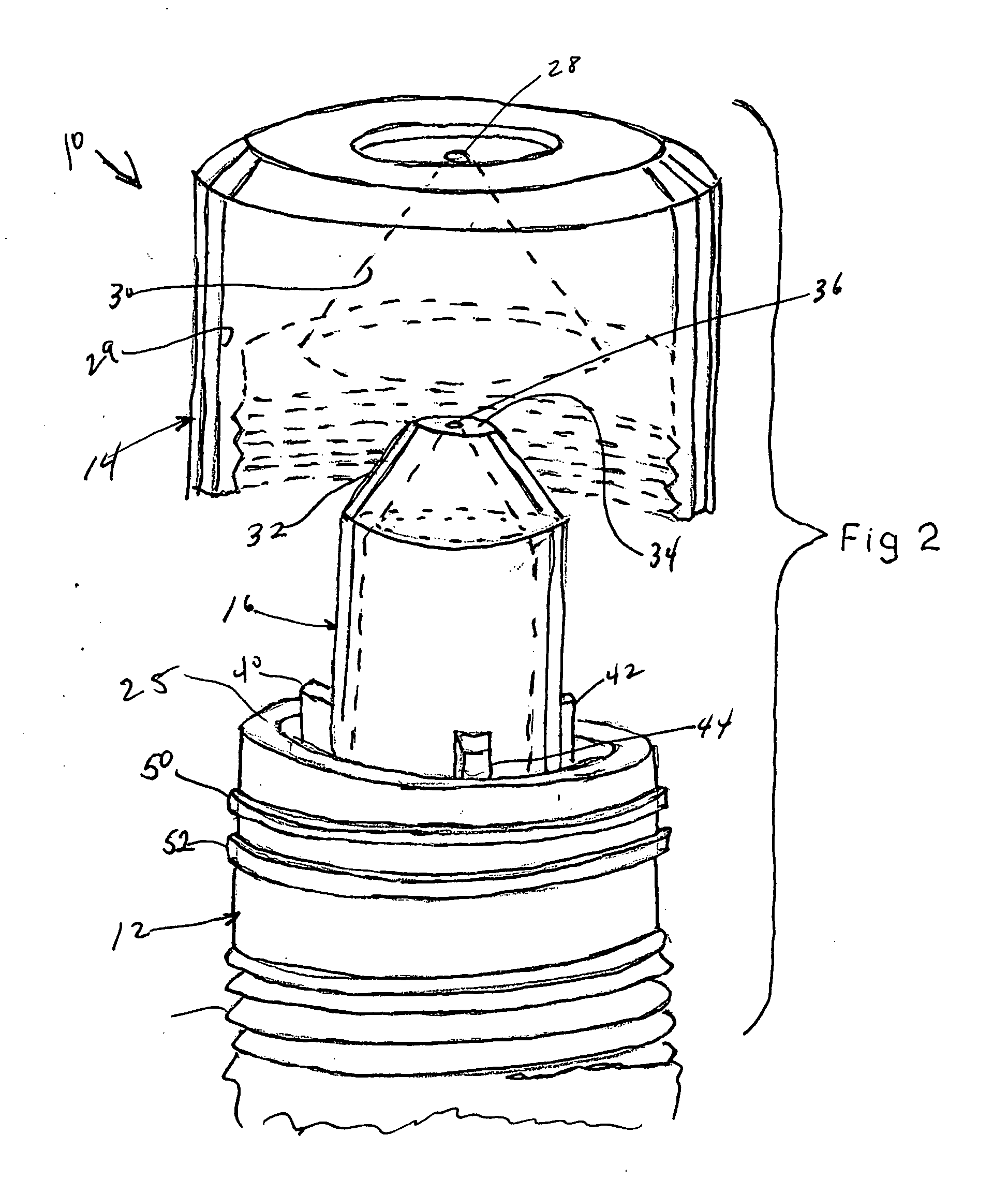
[0012] The adjustable gas nozzle 10 illustrated in the drawings comprises three main elements: a conduit 12 for receiving gas from a source (not illustrated), a nozzle member 14 for supplying a jet of the gas to the burner section of an appliance (not illustrated), and a flow adjusting member 16.

[0013] The nozzle member 14 has a gas passageway 18 which is coaxial therethrough about a longitudinal axis 20 with a threaded inlet opening at a first end 22. The threads 24 on the nozzle body member 14 coact with threads 26 adjacent the open end 25 thereof on the exterior surface of the conduit 12 which is coaxial with the axis of the nozzle body member. A second end of the nozzle body member has a coaxial outlet 28 and the nozzle body member effectively is an annular member having an inner circular surface 29, part of which is a conical surface 30 defining part of the passageway through the nozzle.

[0014] The flow adjusting member 16 has a longitudinal passageway therethrough coaxial wit...


PUM


Abstract

An adjustable gas nozzle has a nozzle body including a passageway therethrough opening into a first orifice at one end and an internal sealing surface adjacent thereto. A threaded internal surface is formed at a second end of the nozzle body. A conduit connected to a source of gas at one end having external threads adjacent a second end is threadably receivable within the second end of the nozzle body and is moveable between the first and second alternative positions relative to the nozzle body. Integral radial ribs are formed externally about the conduit between the external threads and the second end of the conduit and are engageable with the internal surface of said nozzle body between the sealing surface and the threads. The radial ribs on the exterior of the conduit have a larger diameter than the internal diameter of the interior wall of the nozzle body and is of a harder material so that deformation occurs in the wall resulting in a tight seal when the nozzle and the conduit are coupled. A flow adjusting member is supported within the conduit and is moveable toward and away from the orifice of the nozzle body as the nozzle body is threadably moved about the conduit. The adjustment member has an interior passageway which communicates the conduit with the orifice of the nozzle body and has an external surface for cooperatively engaging the sealing surface of the nozzle body in one alternative position and is spaced therefrom in a second alternative position. The flow of gas through the nozzle body orifice varies depending upon which alternative position is selected.

Description

BACKGROUND OF THE INVENTION [0001] This invention relates to a nozzle for gas-heated appliances and more particularly, to a nozzle which may be used with appliances that burn natural gas or liquefied petroleum (LP) gas and which may be used in very high temperature burning environments as well as in lower conventional lower temperature environments. For example, the gas in appliances such as gas water heaters, gas furnaces, gas ovens and gas clothes dryers operate at conventional burning temperatures in the order of approximately 500 degrees to 550 degrees Fahrenheit while the temperature in the cleaning cycle of self-cleaning ovens may be in the order of approximately 900 degrees Fahrenheit. In these high temperature environments, it is important that the seals in the nozzles used to dispense the gas into the combustion chamber of the appliance do not fail or distort so as to prevent the gas from bleeding back and thereafter being drawn into the flame at rates above that desirable ...

Claims


Application Information

Patent Timeline
IPC IPC(8): B05B1/26B05B1/30B05B1/32F23D14/48
CPCF23D14/48
Inventor WARD, KENNETH RAYSWOGGER, OTTO W.
Owner BURNER SYST INT
Why Eureka
Try Eureka