
Synchronization of time-frequency codes

a time-frequency code and synchronization technology, applied in the field of wireless communication, can solve the problems of collisions between different codes, multiple simultaneous operation of piconets (sops), and cannot be guaranteed, and achieve the effect of reducing (or even eliminating) the number of collisions between transmissions

Inactive Publication Date: 2005-08-11
INTELLECTUAL VENTURES I LLC
View PDF19 Cites 150 Cited by
  • Summary
  • Abstract
  • Description
  • Claims
  • Application Information

AI Technical Summary

Benefits of technology

[0009] In aspects of the present invention, the identified frequency hopping pattern and the selected frequency hopping pattern may be the same. Accordingly, the selected timing may provide for no collisions between the identified frequency hopping pattern and the selected frequency hopping pattern. Alternatively, the identified frequency hopping pattern and the selected frequency hopping pattern may be different.
[0013] The present invention advantageously reduces (or even eliminates) the number of collisions between transmissions. Further features and advantages of the present invention will become apparent from the following description and accompanying drawings.

Problems solved by technology

Unfortunately, multiple simultaneously operating piconets (SOPs) are not guaranteed, because, with a limited number of frequency bands, collisions between different codes can happen quite often.

Method used


Image

  • Synchronization of time-frequency codes
  • Synchronization of time-frequency codes
  • Synchronization of time-frequency codes

Examples


Embodiment Construction

I. Frequency Hopping

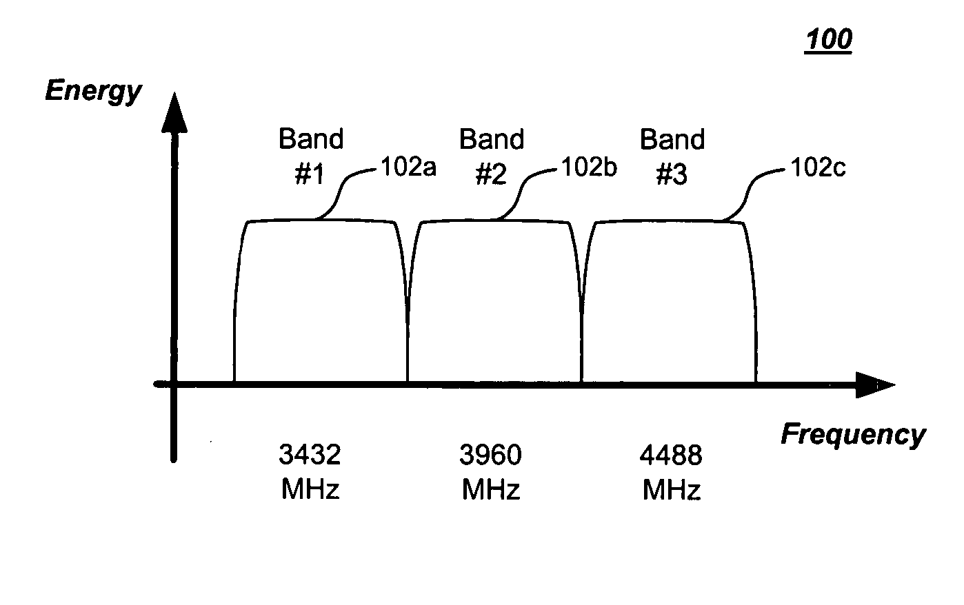
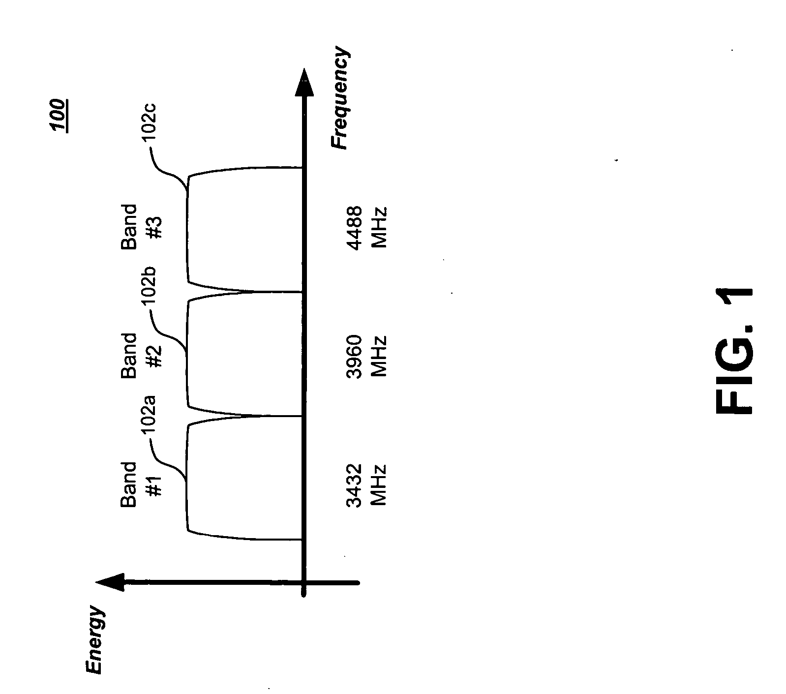
[0027]FIG. 1 is a diagram of an available spectrum 100 for a short-range communications system in which the principles of the present invention may be applied, such as an IEEE 802.15.3a network. As shown in FIG. 1, this spectrum includes three frequency bands 102. In particular, spectrum 100 includes a first band 102a centered at 3432 MHz, a second band 102b centered at 3960 MHz, and a third band 102c centered at 4488 MHz.

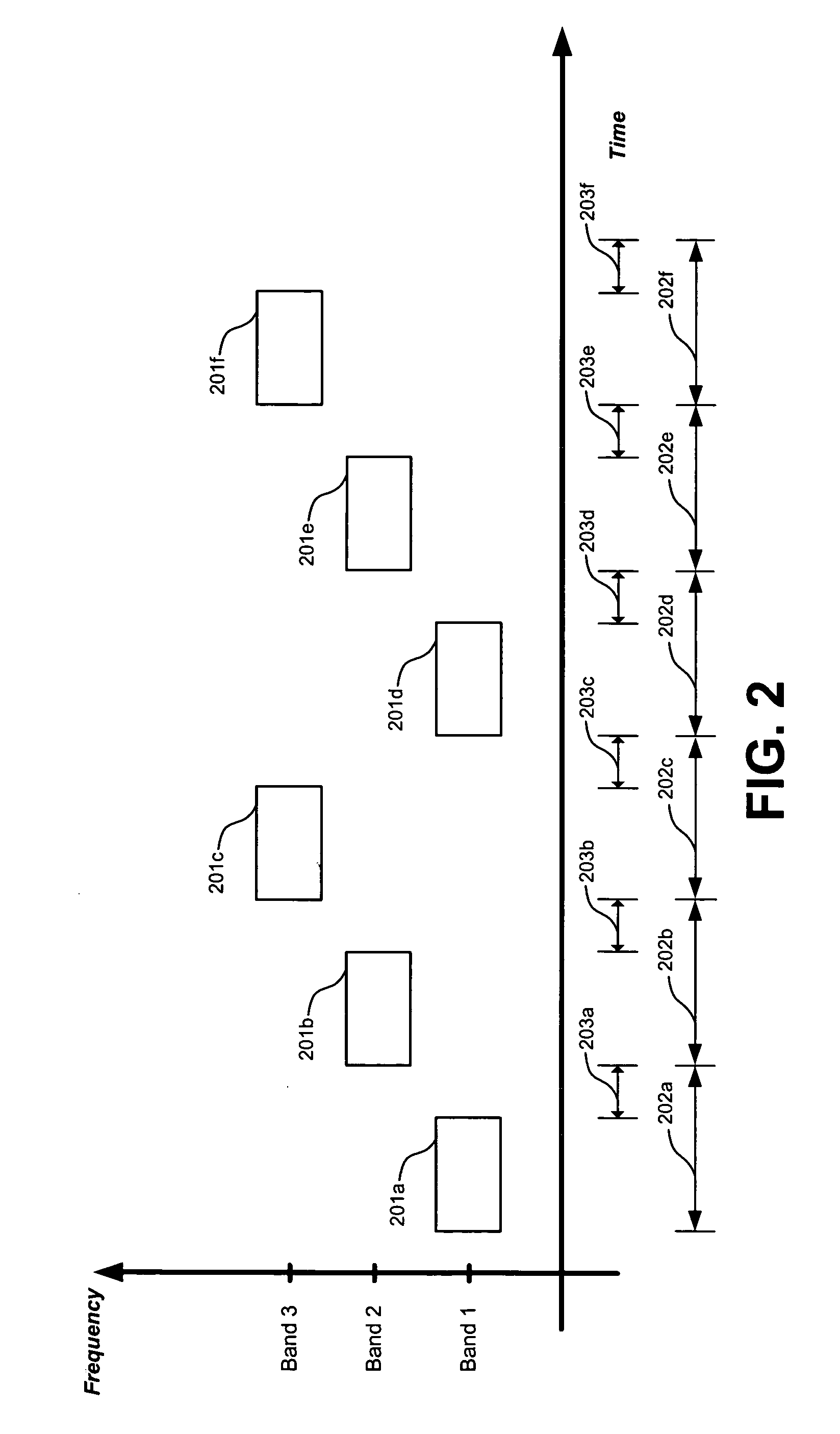
[0028] According to MBO, bands 102 may be used as hopping channels. When used in this manner, each symbol (e.g., each OFDM symbol) is transmitted in one of bands 102 according to a pre-defined code. In IEEE 802.15.3a, such a code is referred to as a time frequency code (TFC). This technique provides for frequency diversity, as well as robustness against multi-path propagation and interference. In addition, this technique allows for multiple-access by utilizing different TFCs for adjacent piconets.

[0029] An example of this frequency-hopping tec...


PUM


Abstract

A frequency hopping pattern associated with a remote short-range wireless communications network is identified. Based on the identified frequency hopping pattern, a frequency hopping pattern for communications in a local short-range wireless communications network is selected. In addition, a timing for the selected frequency hopping pattern is selected based on the identified frequency hopping pattern timing. One or more symbols, such as OFDM symbols, may be transmitted according to the selected frequency hopping pattern and the selected timing.

Description

FIELD OF THE INVENTION [0001] The present invention relates to wireless communications. More particularly, the present invention relates to techniques for controlling the frequency hopping and timing of wireless transmissions. BACKGROUND OF THE INVENTION [0002] Short-range wireless proximity networks typically involve devices that have a communications range of one hundred meters or less. To provide communications over long distances, these proximity networks often interface with other networks. For example, short-range networks may interface with cellular networks, wireline telecommunications networks, and the Internet. [0003] IEEE 802.15.3 defines an ad hoc wireless short-range network (referred to as a piconet) in which a plurality of devices may communicate with each other. One of these devices is called piconet coordinator (PNC), which coordinates timing and other operational characteristics. The remaining devices in the network are known as DEVs. The timing of piconets is base...

Claims


Application Information

Patent Timeline
IPC IPC(8): H04B1/713H04L5/02H04L12/56H04M5/00
CPCH04B1/7143H04L5/023H04W84/10H04W72/02H04W56/00
Inventor PALIN, ARTOREUNAMAKI, JUKKA
Owner INTELLECTUAL VENTURES I LLC
Learn More