Switch machine with improved switch point connectors

a switch machine and connector technology, applied in railway signalling and safety, roads, construction, etc., can solve the problems of switch machine locking up and not applicable to the operation of switch points of interconnected types

Inactive Publication Date: 2005-08-18
GENERAL ELECTRIC CO
View PDF11 Cites 15 Cited by
  • Summary
  • Abstract
  • Description
  • Claims
  • Application Information

AI Technical Summary

Benefits of technology

[0012] In accordance with the present invention, a pivoting connector assembly is provided on the outer end of each operating rod. In one form of the invention, a socket mounted or formed on the outer end of the operating rod has a vertically oriented bore into which a pivot shaft is positioned, with a collar at the top of the vertical pivot shaft. A horizontal bore is formed in the collar, and the collar bore is adapted to pivot about the vertical axis of the pivot shaft. A horizontal pivot pin is attached essentially parallel to each switch point. This pivot pin is positioned through the collar bore, in a sliding arrangement. As the operating rod moves the switch point laterally, the collar slides along the horizontal pivot pin by a slight amount. Further, as the switch point moves laterally, the collar pivots about the vertical axis to maintain the alignment of the collar bore axis with the horizontal axis of the pivot pin. This prevents the pivot pin from imposing a lateral reactive force on the operating rod.

Problems solved by technology

The device described in that patent operates switch points which are independent, or disconnected, from each other, and it is not applicable to the problem of operating switch points of the interconnected type, i.e. of switch points connected to each other by transverse bars.
This lateral reactive force can cause premature failure of the seal and binding of the operating rod relative to the housing, which can cause the switch machine to lock up.

Method used


Image

  • Switch machine with improved switch point connectors
  • Switch machine with improved switch point connectors
  • Switch machine with improved switch point connectors

Examples


Embodiment Construction

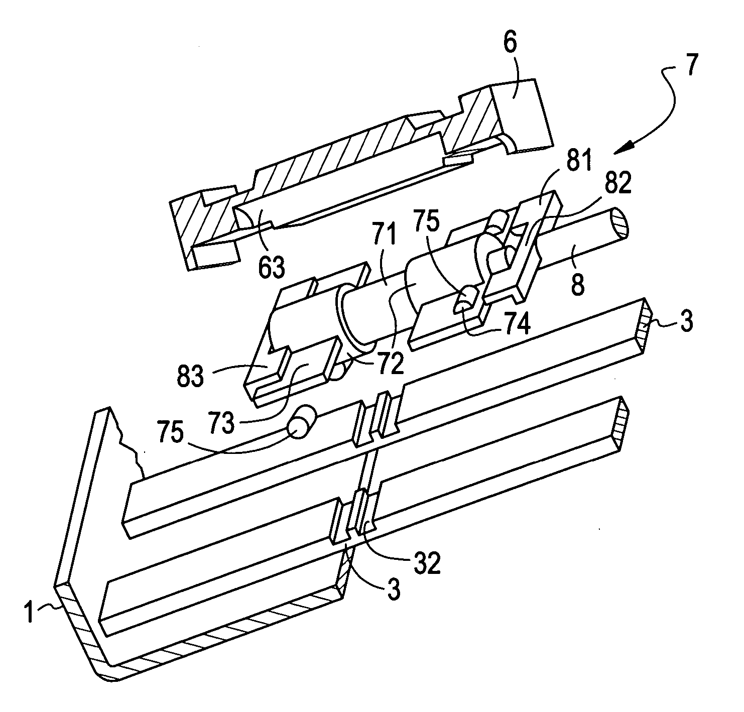
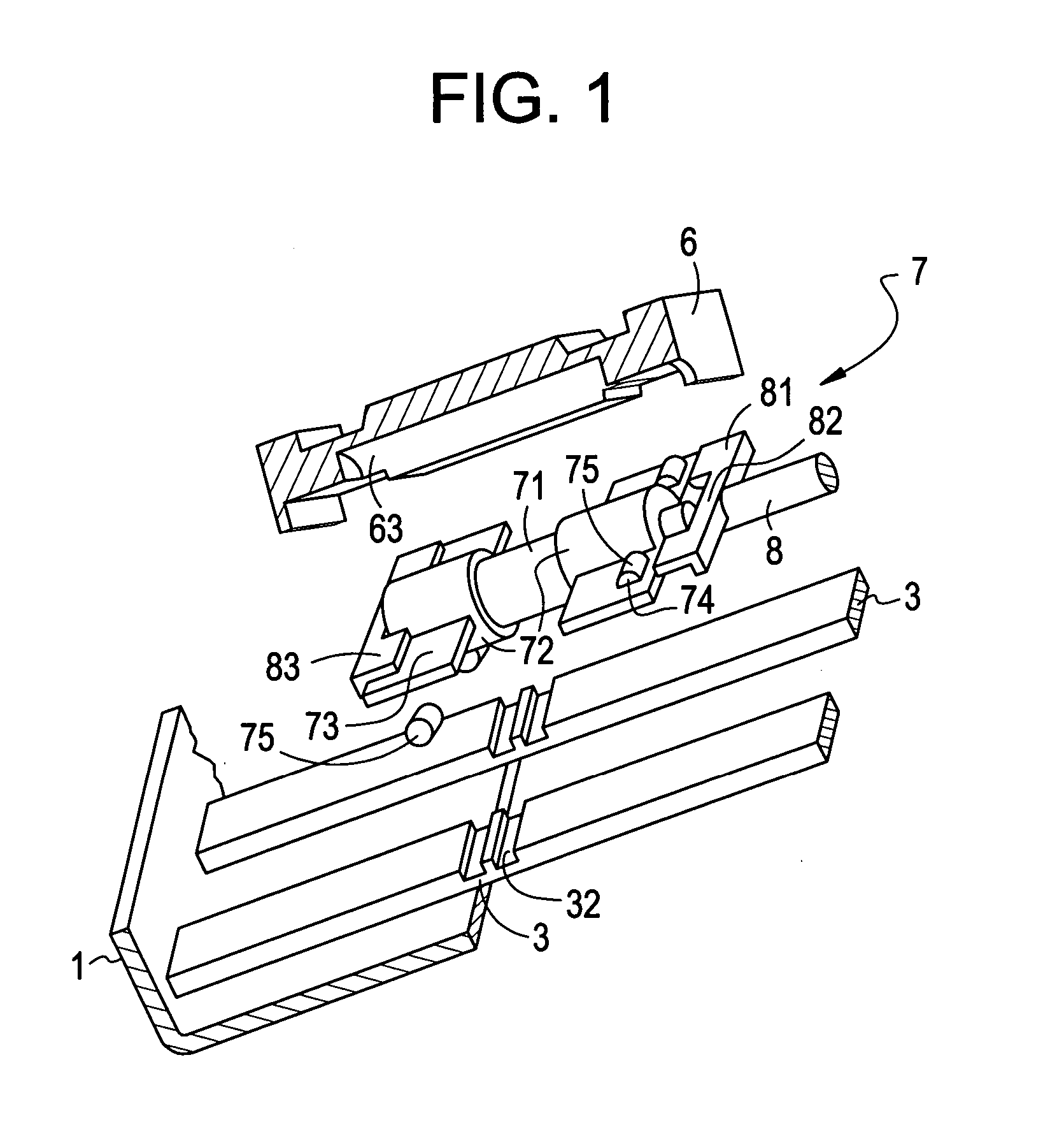
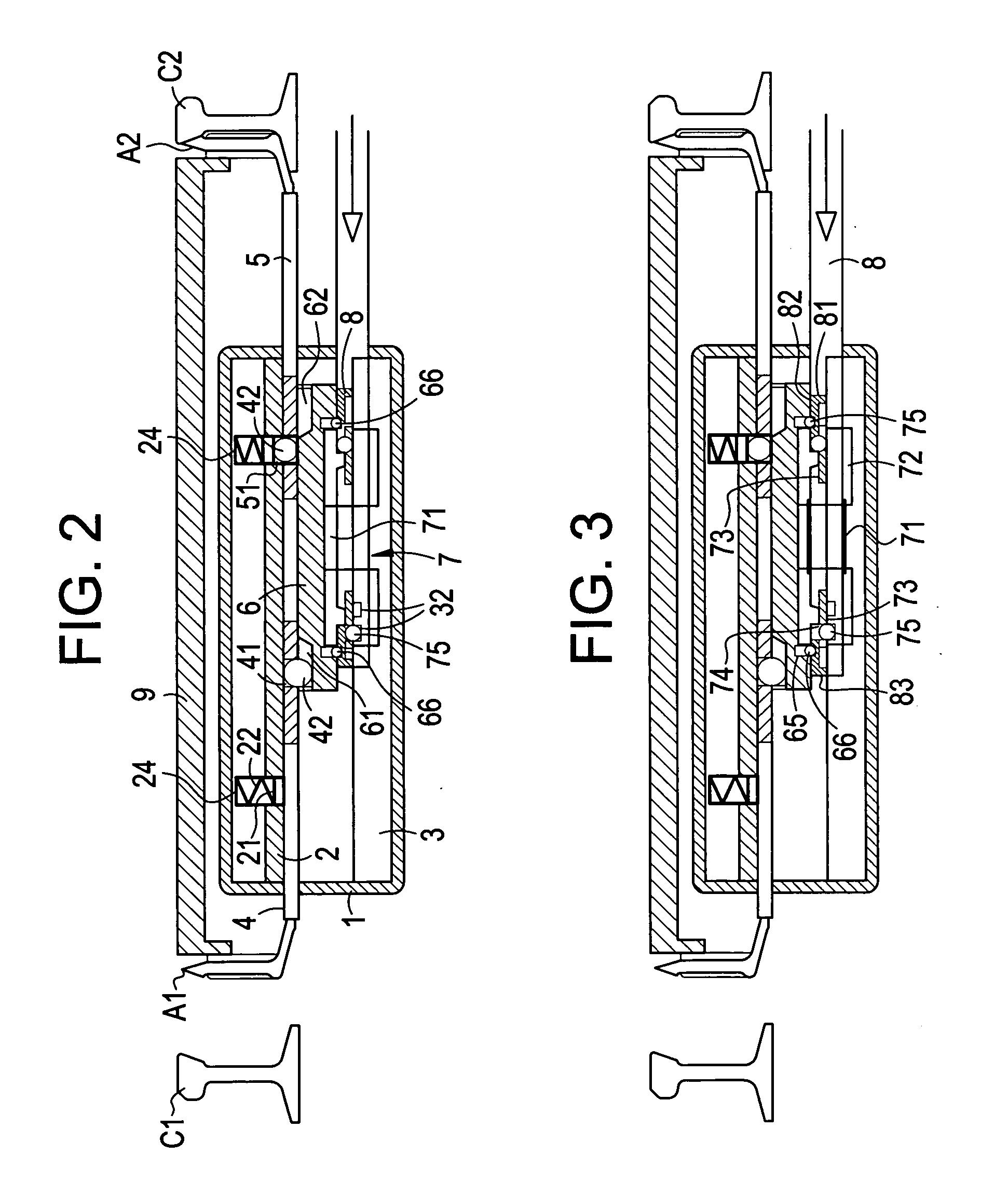
[0026] As seen in the attached drawings, the switch machine includes three basic types of fixed components: a fixed housing 1; a plate 2 fixedly mounted within or otherwise attached to the housing 1; and two guides 3 fixedly mounted within or otherwise attached to the housing 1, below the level of the fixed upper plate 2. A capture mechanism, including a plurality of capture elements and a shifting body, is used to selectively engage and disengage two operating rods 4, 5 to and from the fixed upper plate 2. More specifically, an upper set of interlocking or capture elements are provided to selectively interlock or engage the two operating rods 4, 5 with either the fixed upper plate 2 or the shifting body within the housing 1. As part of the upper set of interlocking elements, the fixed upper plate 2 is provided with two ball seats 24 mounted on the upper side thereof. Each of the ball seats 24 houses a corresponding disk or follower plate 21 which can be completely inserted in its r...


PUM


Abstract

A switch machine for a railroad switch provided with two switch points, including two operating rods extending from the housing to the switch points; a shifting body within the housing, capable of sliding relative to the housing to simultaneously displace the operating rods; an engagement device within the housing for selectively engaging the operating rods to the housing at the two end stroke points; and a pivoting connector between each operating rod and its associated switch point.

Description

CROSS REFERENCE TO RELATED APPLICATIONS [0001] Not Applicable STATEMENT REGARDING FEDERALLY SPONSORED RESEARCH OR DEVELOPMENT [0002] Not Applicable BACKGROUND OF THE INVENTION [0003] 1. Field of the Invention [0004] The present invention is in the field of railroad switching devices, namely the equipment which is used to displace railroad switch points. More specifically, the invention refers to a pivoting connector which connects each of the operating rods of the switching device to the associated switch point, in a non-binding relationship. [0005] 2. Background Art [0006] A railroad switch point consists of tapered rail sections which are capable of being selectively displaced between two different lateral positions at a rail switch and then locked in the selected position, in order to facilitate the desired routing of a train passing through the switch. The two switch points are typically displaced by rods extending from an assembly which is referred to herein as a “switch machin...

Claims


Application Information

Patent Timeline
Patent Type & Authority Applications(United States)
IPC IPC(8): B61L5/00E01B7/02
CPCB61L5/00
Inventor BIAGIOTTI, MAURIZIO
Owner GENERAL ELECTRIC CO
Why Eureka
Try Eureka