
Driving mechanism for the traction-exerting component particularly of a conveyor device

Inactive Publication Date: 2005-08-25
TGW TRANSPORTGERAETE
View PDF15 Cites 19 Cited by
  • Summary
  • Abstract
  • Description
  • Claims
  • Application Information

AI Technical Summary

Benefits of technology

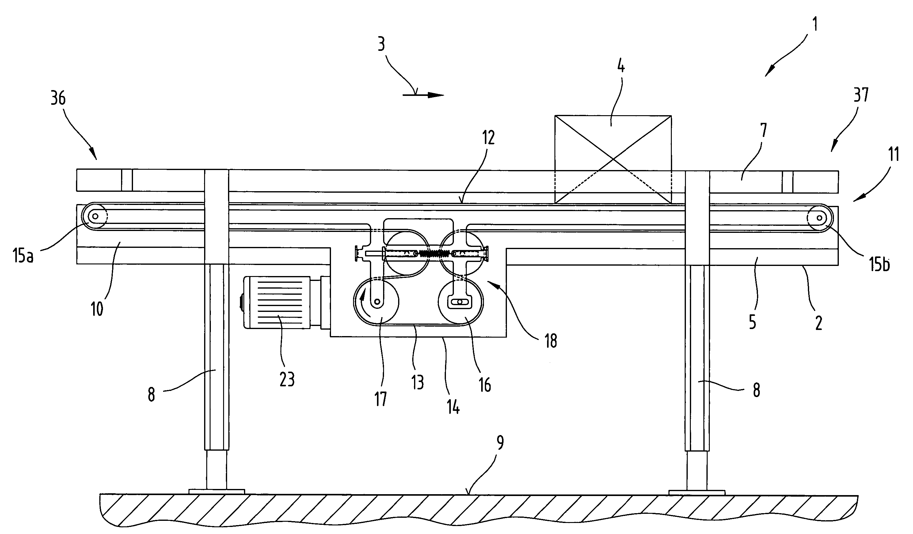
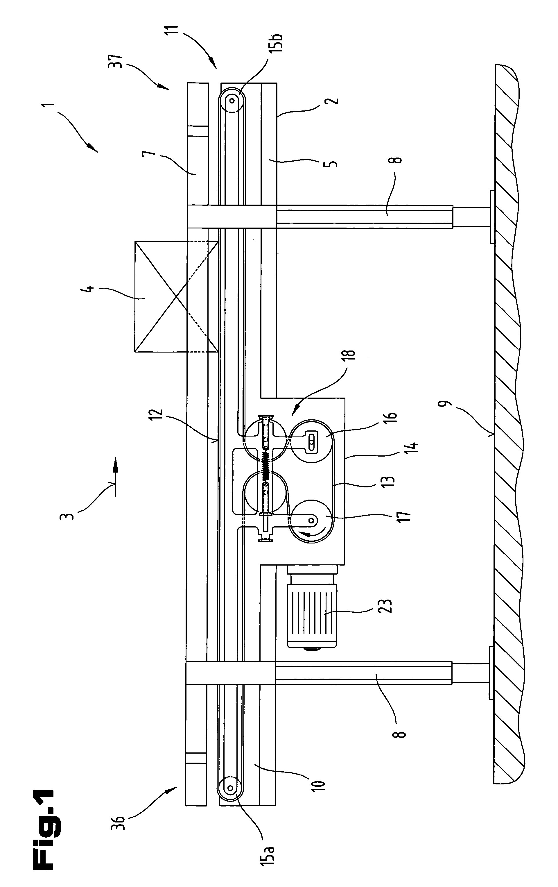
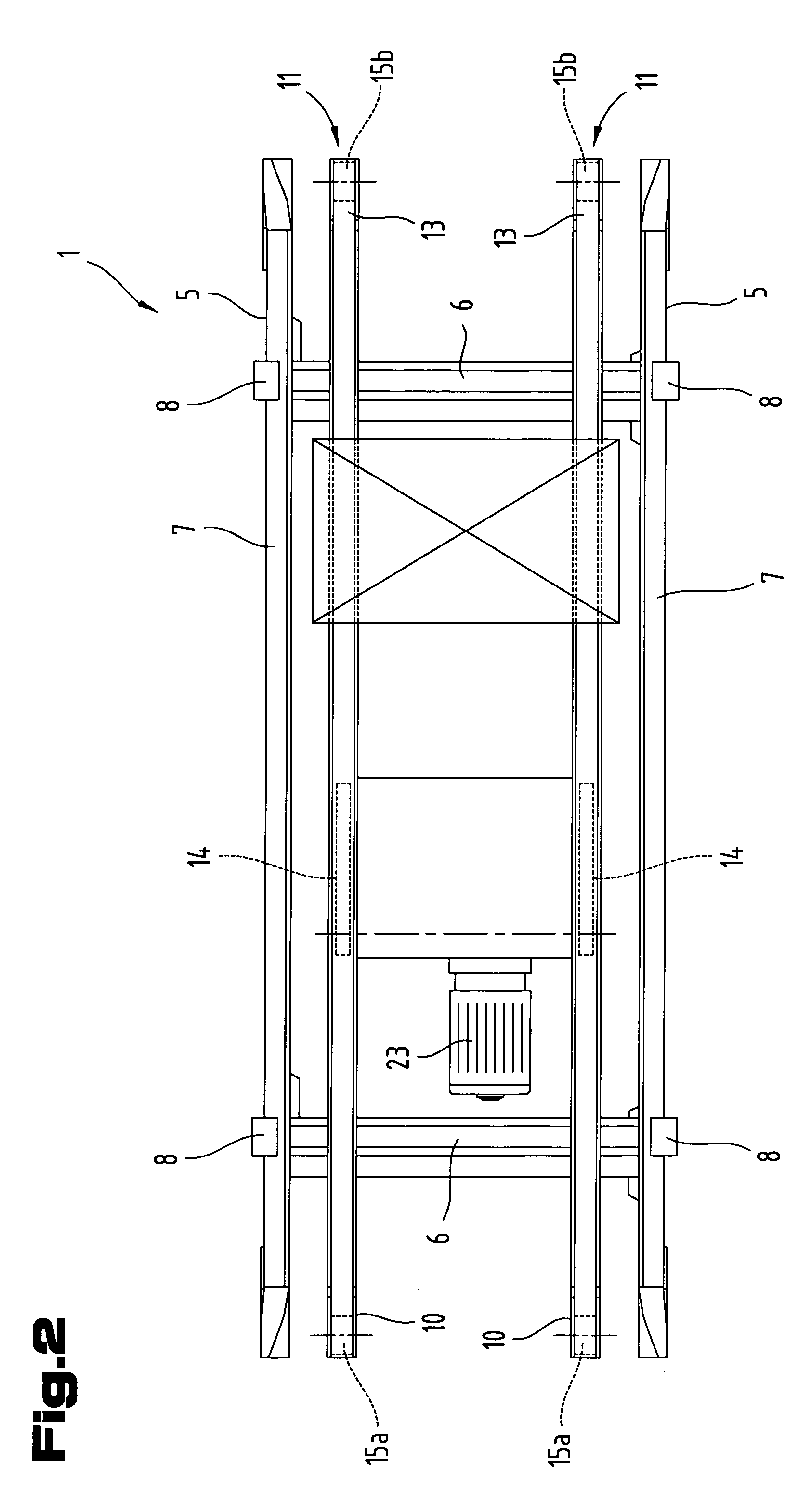
[0013] The problem of the invention is resolved in that the support bodies are coupled with each other in terms of movement via the setting elements. The benefits so gained are surprising in that both in the normal (clockwise operation of the traction-exerting component) and the reverse operations (anticlockwise operation of the traction-exerting component), a tensioning element is in contact with the pulled strand, whereas the other tensioning element is in contact with the returning strand, and in that the tension applied to the traction-exerting component on the returning strand is automatically maintained irrespectively of in which mode of operation or direction of revolution the traction-exerting component is operating. If a flat type or a V-belt or some other type of belt or band or a cable or the like is employed as the traction-imparting component, it is now possible to transmit the peripheral force in a simple manner from the driving wheel to the traction-exerting component free of slip. If the traction-exerting component is realized in the form of a chain, toothed belt and the like, the tension in the traction-exerting component is automatically maintained, and vibration of the chain causing wear is avoided. In addition, lengthening of the traction-exerting component caused by the operating load, as well as also extension of said component due to aging in the course of operation of the driving mechanism for the traction-exerting component is continually compensated via the tensioning element contacting the returning strand, and the tension in the traction-exerting component remains automatically maintained without requiring re-tensioning from time to time. Manual retensioning of the traction-exerting component at periodic maintenance time intervals can be avoided in this way. The tension in the traction-exerting component is generated in a beneficial way via at least one setting element arranged on the frame of support bodies that are supported in a floating manner.
[0031] Finally, the problem of the invention is resolved also by the features specified in claim 32. It is advantageous that piece goods can be transported on the conveyor device selectively from the left to the right and from the right to the left with no change in the conveying properties, in particular in the peripheral force, conveying rate and the like, and that as a result of the compact structure of the tensioning system, trouble-free operation of the conveyor system is achieved without the necessity of manual re-tensioning from time to time.

Problems solved by technology

This requires the tensioning force acting on the tensioning wheels to be rated unnecessarily high, and the efficiency of the setting cylinder employed in such a system has to be rated high accordingly.

Method used


Image

  • Driving mechanism for the traction-exerting component particularly of a conveyor device
  • Driving mechanism for the traction-exerting component particularly of a conveyor device
  • Driving mechanism for the traction-exerting component particularly of a conveyor device

Examples


Embodiment Construction

[0047] It is noted by way of introduction that in the different exemplified embodiments described herein, identical components are provided with identical reference numbers or identical component designations, whereby disclosures contained throughout the specification are applicable in the same sense to identical components with identical reference numbers or identical component designations. Furthermore, data selected in the specification for positions such as, for example top, bottom, lateral etc., relate to the directly described and shown figure, and, where a position has changed, have to be applied to the new position in the same sense. Moreover, individual features or combinations of features in the various exemplified embodiments shown and described herein may represent independent inventive solutions or solutions as defined by the invention.

[0048] The jointly described FIGS. 1 and 2 show various simplified views of a possible design variation of a conveyor device 1, particu...


PUM


Abstract

The invention relates to a driving mechanism (11) for the traction-exerting component (13) of a conveyor device (1), with a frame (10); at least one reversing wheel (15a, 15b) and one driving wheel (17) supported on said frame; an endlessly revolving, flexible traction-exerting component (13) guided around the reversing and driving wheels (15a, 15b; 17) and having a pulled strand and a returning strand; a tensioning device (18); as well as a setting device comprising the tensioning device. The tensioning device (18) has two support bodies arranged one behind the other in the direction of revolution of the traction-exerting component (13), said support bodies being adjustable against one another, and tensioning elements each supported on said support bodies. With its pulled strand, the traction-exerting component (13) is guided around one of the tensioning elements, and with its returning strand around the other tensioning element, as well as around the reversing and driving wheels (15a, 15b; 17), whereby tensioning forces directed against each other are admitted to the tensioning elements, which are arranged spaced from each other; and whereby the spacing is adjustable to a limited extent via the at least one setting element.

Description

CROSS REFERENCE TO RELATED APPLICATIONS [0001] Applicant claims priority under 35 U.S.C. §119 of AUSTRIAN Patent Application No. A 201 / 2004 filed on 11 Feb., 2004. BACKGROUND OF THE INVENTION [0002] 1. Field of the Invention [0003] The invention relates to a driving mechanism for the traction-exerting component particularly of a conveyor device, comprising a frame; at least one reversing wheel and one driving wheel supported on said frame; an endlessly revolving flexible traction-exerting conveyor component that is reversible with respect to its direction of revolution and has a pulled strand and a returning strand; a tensioning device, as well as at least one setting element, such tensioning device comprising two support bodies arranged one after the other in the direction of revolution of the traction-imparting component, and being adjustable relative to each other; and tensioning elements each being supported on said support bodies, whereby tensioning forces are directed at each ...

Claims


Application Information

Patent Timeline
IPC IPC(8): B65G23/44
CPCB65G23/44
Inventor ANGLEITNER, KARL
Owner TGW TRANSPORTGERAETE
Learn More