Clamping apparatus and method

a technology of clamping apparatus and clamping method, which is applied in the direction of hose connection, machine support, other domestic objects, etc., can solve the problems of difficult clamping, difficult clamping installation, and requiring more time and effort, and achieve the effect of easy installation

Active Publication Date: 2005-09-01
GOLDMAN SACHS BANK USA AS SUCCESSOR COLLATERAL AGENT +1
View PDF16 Cites 17 Cited by
  • Summary
  • Abstract
  • Description
  • Claims
  • Application Information

AI Technical Summary

Benefits of technology

[0010] The foregoing needs are met, to a great extent, by the present invention, wherein in one aspect an apparatus is provided that in some embodiments allows for easy installation, is ergonomically favorable, lockable, stackable, rotatable, lightweight, inexpensive and can be used repeatedly under any application.

Problems solved by technology

There are many disadvantages to the typical loop clamp.
The clamps are difficult to install and therefore require more time and effort.
The typical loop clamp is ergonomically undesirable in that repeated installation of the clamp results in carpal tunnel injuries for the operators.
Also, many loop clamps are heavy and cannot be rotated or stacked when installed.
These clamps have a limited life in that repeated use may not be possible.
The frequent removal and installation may cause fatigue on the clamp band and may lead to complete failure of the clamp.
This is very undesirable especially in aircraft applications.
In addition, such failures result in increased cost.
However, traditional clamps may not be reused on engines, such as aircraft turbojets, because of the immense heat cycling and vibration.
Installing and removing wires, ducts and the like from traditional clamps can be cumbersome.
Traditional loop clamp openings are not very wide and require a considerable amount of effort to be opened.
Once opened, conventional loop clamps undergo metal fatigue and are subject to additional fatigue or failure when closed.
In addition, the cushions that often are used with these clamps slip off or do not provide the amount of cushioning required, leading to greater abrasion and vibration.

Method used


Image

  • Clamping apparatus and method
  • Clamping apparatus and method
  • Clamping apparatus and method

Examples


Embodiment Construction

[0021] The invention will now be described with reference to the drawing figures, in which like reference numerals refer to like parts throughout. An embodiment in accordance with the present invention provides a universal clamp that allows for easy installation, is ergonomically favorable, lockable, stackable, rotatable, lightweight, inexpensive and can be used repeatedly.

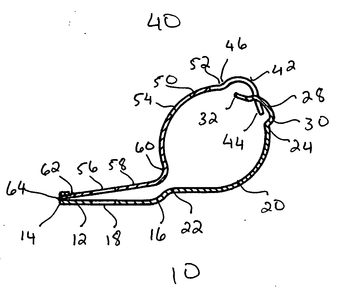
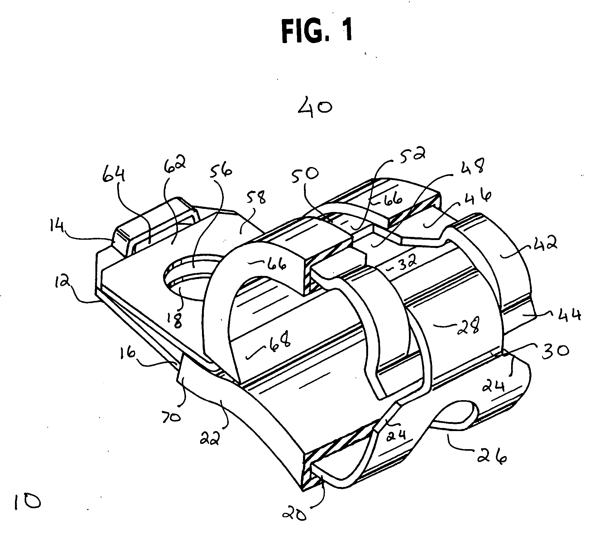
[0022]FIG. 1 is an isometric view of the preferred embodiment of the present invention. This figure depicts the device having a bottom half clamp 10. The bottom half clamp 10 has a bottom planar surface 12. The bottom planar surface 12 has an opening 14, configured to mate or accept another device at a first planar end 15, and a second planar end 16. Located on the bottom planar surface 12 are edges defining an opening or a bottom planar hole 18.

[0023] The bottom half clamp 10 has a first curved surface 20. The first curved surface 20 has a first curved end 22 that attaches to the second planar end 16 of the bot...


PUM


Abstract

A clamping method and apparatus including two halves of a clamp mated at a first end. The two halves are pivotally connected at a second end. The present invention is configured to permit the device to be repeatedly used without extended wear.

Description

CROSS-REFERENCE TO RELATED APPLICATIONS [0001] This application claims priority to provisional U.S. patent application entitled, Universal Clamp, filed Feb. 20, 2004, having an application No. 60 / 545,946 now pending, the disclosure of which is hereby incorporated by reference in its entirety.FIELD OF THE INVENTION [0002] The present invention relates generally to retaining mechanisms. More particularly, the present invention relates to a clamp that includes a top and bottom portion such that these pieces are mated at one end and pivotally connected at another. BACKGROUND OF THE INVENTION [0003] There are many clamping devices that exist for retaining wires and the like for many different applications. They include cushioned and uncushioned loop clamps, hose clamps and snapper type clamps, among others. The loop clamp is common in the aircraft and automotive industries, for both original equipment manufacturing as well as aftermarket sectors. These clamps are often used to attach pod...

Claims


Application Information

Patent Timeline
Patent Type & Authority Applications(United States)
IPC IPC(8): F16B2/10F16L3/10F16L33/00
CPCF16B2/10Y10T24/14Y10T24/1457F16L3/1025
Inventor SHARKEY, BRIAN
Owner GOLDMAN SACHS BANK USA AS SUCCESSOR COLLATERAL AGENT
Why Eureka
Try Eureka