Network facsimile system

a network facsimile and facsimile technology, applied in computing, digital output to print units, instruments, etc., can solve the problems of inability to know the status from the origin station to the relaying server in real time, error in the transmission from the relaying server,

Inactive Publication Date: 2005-09-01
BROTHER KOGYO KK
View PDF42 Cites 34 Cited by
  • Summary
  • Abstract
  • Description
  • Claims
  • Application Information

AI Technical Summary

Benefits of technology

[0011] Aspects of the present invention are advantageous in that, in a network facsimile system employing a relaying server through which facsimile images are transmitted from an origin station to a destination station, “transparency” of the relaying server can be realized. Thus, users of the origin station and the destination station can use the network facsimile system as a normal facsimile system using the facsimile machines connected through the telephone line. These and other aspects of the invention are described below.

Problems solved by technology

Firstly, the user at the origin station can know the transmission status from the origin communication terminal to the relaying server, but cannot know the status from the relaying server to the destination station in real time.
Secondly, the user of the destination station can know the transmission status from the relaying server to the destination communication terminal, but cannot know the status from the origin station to the relaying server in real time.
Therefore, even if the transmission from the origin station to the relaying server is completed successfully, there could be a case where an error occurs in the transmission from the relaying server to the destination station.
Further, when an error occurs in the transmission from the relaying server to the destination, it is recognized by the user of the destination station.
However, if an error occurs in the transmission from the origin station to the relaying server, the user of the destination station would not know the attempt of transmission directed to the destination station, which would not occur in the normal facsimile system.

Method used


Image

  • Network facsimile system
  • Network facsimile system
  • Network facsimile system

Examples


first embodiment

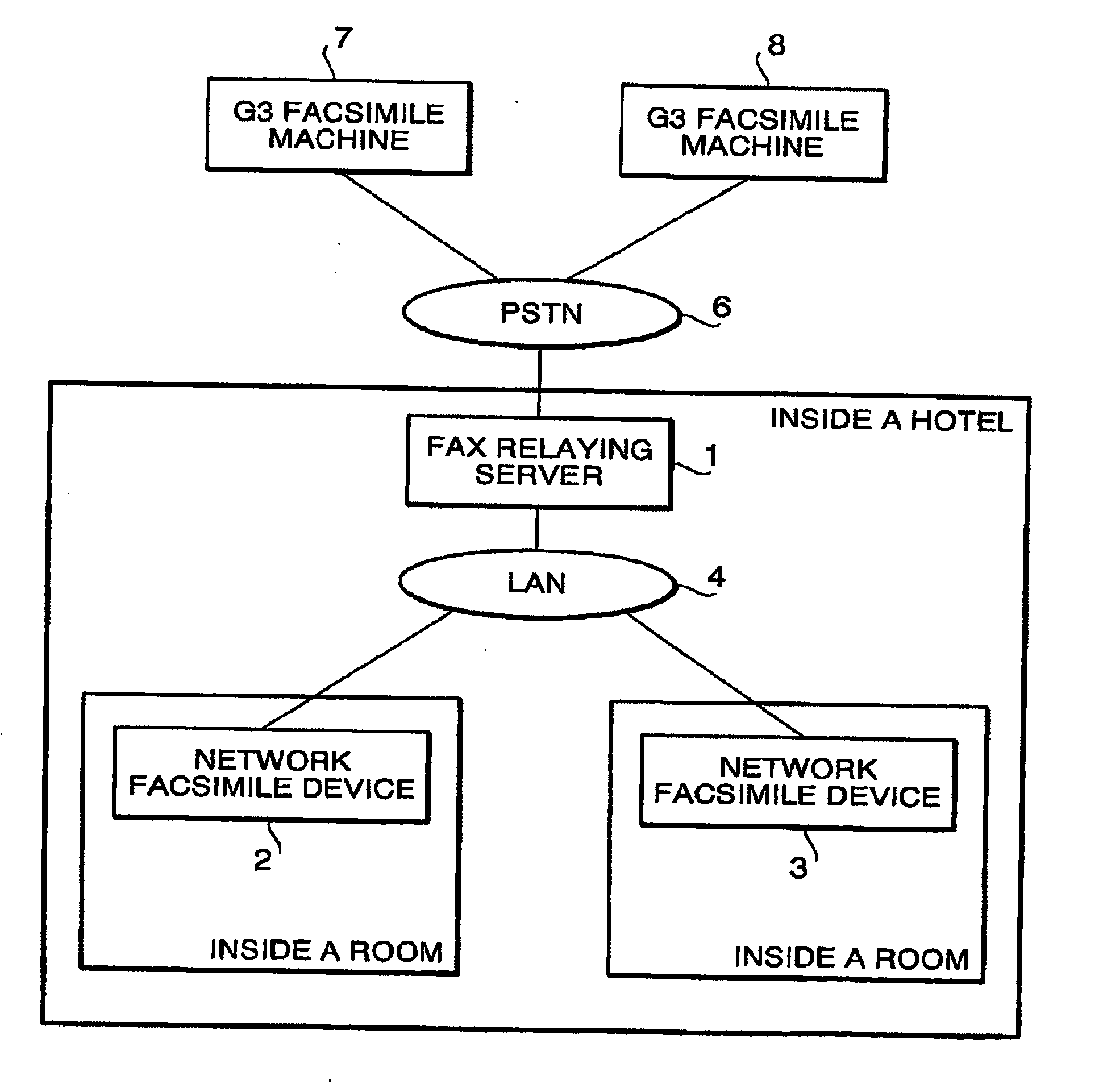
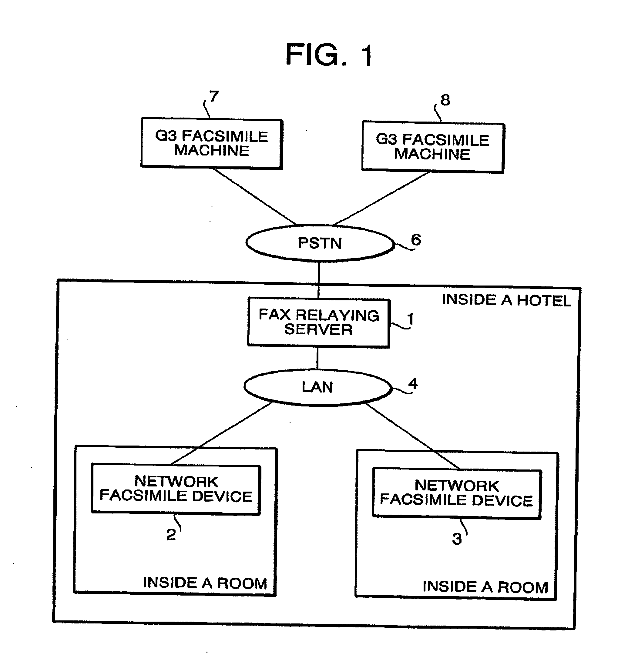
[0075] A network facsimile system according to a first embodiment will be described. The network facsimile system is a system employed in a hotel having a plurality of rooms. FIG. 1 is a block diagram showing an entire configuration of the network facsimile system

[0076] As shown in FIG. 1, in the hotel, a facsimile relaying server 1 (hereinafter, referred to as a FAX relaying server), network facsimile devices 2 and 3 are provided and are connected through a LAN (Local Area Network) 4 to constitute the network facsimiles system.

[0077] The FAX relaying server 1 is connected with a PSTN (public switched telephone networks) 6. Accordingly, the FAX relaying serer 1 is capable of transmitting / receiving images to / from a facsimile machine (e.g., G3 facsimile machines 7 and 8) outside the network facsimile system.

[0078] It should be noted that there are a plurality of network facsimile devices, which are implemented in hotel rooms one for each. Since they have functionally the same, only...

second embodiment

[0196] Hereinafter, a network facsimile system according to a second embodiment will be described. Since the configuration of the second embodiment is close to the first embodiment, in the following description, different portions will be described in detail and portions of the second embodiment having the configuration similar to the first embodiment will be omitted.

[0197] In the first embodiment, the facsimile data transmitted by the origin station outside the network facsimile system is received by the FAX relaying server 1, which converts the received facsimile data into an entail message and transmits the evil message to the network facsimile device 2. Since the FAX relaying server 1 and the network facsimile device 2 can exchange electronic data using a predetermined communication protocol. Therefore, the FAX relaying server 1 and the network facsimile device 2 can exchange data in accordance with a communication protocol other than the e-mail communication protocol.

[0198] I...

third embodiment

[0214] Hereinafter, a network facsimile system according to a third embodiment of the invention will be described. In the third embodiment, the FAX relaying server 1 is configured such that a plurality of facsimile transmission requests from a plurality of network facsimile devices are handled parallelly (i.e., simultaneously).

[0215] Specifically, the FAX relaying server 1 employs a multi-task OS, and with the function of the multitask OS, the FAX relaying server 1 is capable of executed a plurality of tasks parallelly in a time-sharing manner. According to the third embodiment, the SMTP reception module 41 (see FIG. 3) is configured to have plurality of similar tasks each executes an e-mail receiving process. With this configuration, the FAX relaying server 1 is capable of receiving a plurality of e-mail messages respectively transmitted from a plurality of network facsimile devices. Further, the FAX communication management module 52 (see FIG. 3) includes a plurality of similar t...


PUM


Abstract

A network facsimile system has a communication terminal and relaying server. The network facsimile system is configured such that the communication terminal can transmit an image, through the relaying server, to a destination terminal outside the network facsimile system, that the communication terminal transmits an image to the relaying server in accordance with a predetermined communication protocol. The relaying server transmits an image to the destination terminal in accordance with a facsimile communication protocol. The communication terminal includes a notification system that notifies a user of the communication terminal of an operation status information indicating an operation status of the network facsimile system during a relaying server side operation period.

Description

INCORPORATION BY REFERENCE [0001] This application claims priority from Japanese Patent Application No. 2004-054216, filed on Feb. 27, 2004, the entire subject matters of the application are incorporated herein by reference thereto. BACKGROUND OF THE INVENTION [0002] 1. Technical Field [0003] Aspects of the present invention relate to a network facsimile system that transmits / received images to / from an external device in accordance with a facsimile data transmission protocol. [0004] 2. Related Art [0005] Conventionally, a facsimile system in which a facsimile image is transmitted from an origin station to a destination station via a relaying server has been known. In such a system, the relaying server receives the facsimile image from the origin station and transmits the same to the destination station. [0006] United States Patent Application Publication No. U.S. 2002 / 0069254 A1 discloses a method for an e-mail transmission control. According to this publication, the server receives...

Claims


Application Information

Patent Timeline
Patent Type & Authority Applications(United States)
IPC IPC(8): G06F13/00H04M11/00H04N1/00H04N1/32
CPCH04N1/00209H04N2201/0018H04N2201/0017H04N1/00212
Inventor NAKAMURA, MICHIHIRO
Owner BROTHER KOGYO KK
Why Eureka
Try Eureka