LCD optical waveguide device

a technology of optical waveguide and optical waveguide light, which is applied in the direction of waveguides, optical waveguide light guides, instruments, etc., can solve the problems of increasing the production cost of diffusers, the complexity of manufacturing processes, and the inability to accurately correct phenomena. the effect of increasing the spacing

Inactive Publication Date: 2005-09-08
K-BRIDGE ELECTRONICS CO LTD
View PDF3 Cites 17 Cited by
  • Summary
  • Abstract
  • Description
  • Claims
  • Application Information

AI Technical Summary

Benefits of technology

[0007] The primary purpose of the present invention is to provide an improved structure of an optical wave-guide device to effectively solve the problem of the bright band and dark band on the LCD of the LCD and reduce the spacing between light sources and a lower diffuser sheet to make the backlight module thinner for meeting compact requirements of the LCD by replacing the diffuser plate with an optical wave-guide device. To achieve the purpose, the optical wave-guide device is provided between light sources and a lower diffuser sheet for the lights passing through the optical wave-guide device to be properly refracted and reflected to evenly diffuse via the lower diffuser sheet in providing an active solution.

Problems solved by technology

Whereas the diffuser plate 30 functions only to help achieve the even diffusion for lights passing through it, it has a limited efficiency in correcting the phenomenon of the bright band and the dark band observed on the LCD.
However, the structural design for such an improvement not only provides limited effects but also results in that the backlight module must be made thicker to fail the compact requirements of the LCD.
Again, the extinction process not only increases the production cost of the diffuser and the complexity of the manufacturing process, but also relates to a passive solution to reduce the dark band on LCD since the extinction is created only after the light lands on the surface of the diffuser.

Method used


Image

  • LCD optical waveguide device
  • LCD optical waveguide device
  • LCD optical waveguide device

Examples


Embodiment Construction

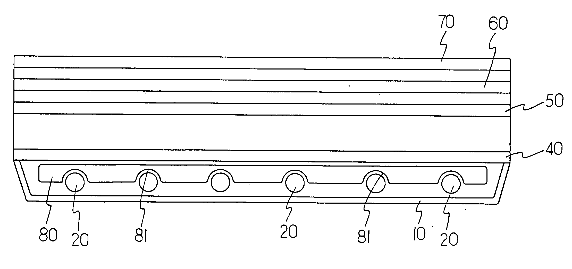
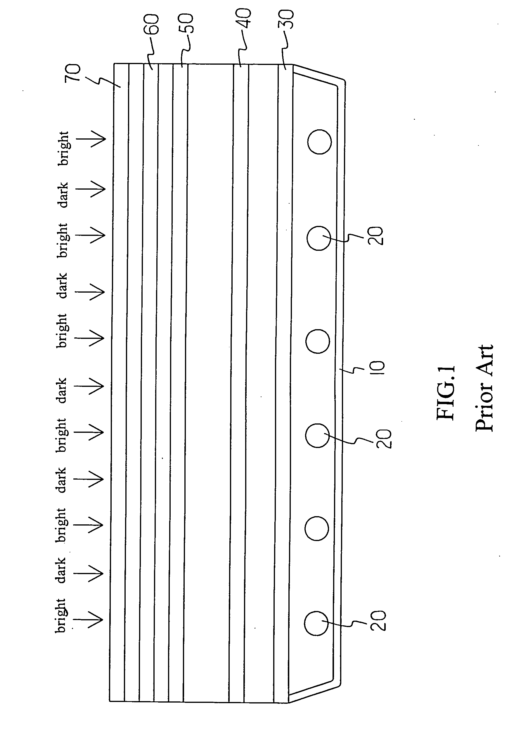
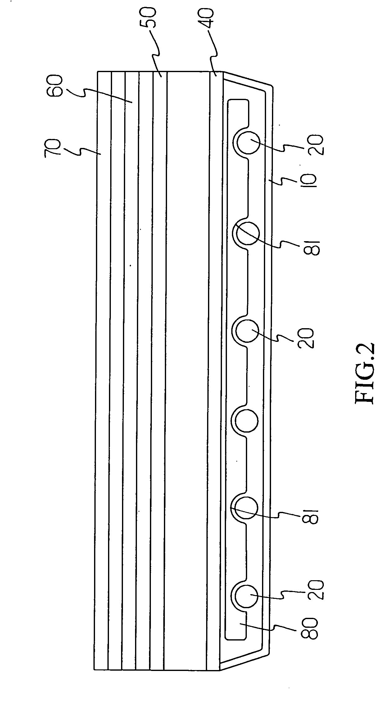
[0013] Referring to FIG. 2, a first preferred embodiment of the present invention is essentially comprised of the backlight module is essentially comprised of a reflector mask 10, multiple light sources 20,a diffuser plate 30, a lower diffuser sheet 40, a prism 50, a reflective polarizing sheet or an upper diffuser 60 and a protector sheet 70 arranged in sequence from inside out. Wherein, those light sources 20 may be each a light tube in a stripe, U-shape or other continuously curve and arranged at a proper spacing between the reflector mask 10 and the lower diffuser sheet and the lights emitted by each of those light sources 20 provide the display effects by the LCD.

[0014] At least one optical wave-guide device 80 is separately provided between those light sources 20 and the lower diffuser sheet 50. The optical wave-guide device 80 is made into a plate and provided with multiple recesses 81 each to accommodate respective light source 20, and the light emitted from each light sour...


PUM


Abstract

An optical wave-guide device is provided between light source and the lower diffuser for the light passing through the optical wave-guide device to form proper deflection and reflection to be consistently diffused through the lower diffuser without creating any blind area among light sources to effectively solve the problem of displaying bright band and dark band on the LCD of the prior art.

Description

BACKGROUND OF THE INVENTION [0001] (a) Field of the Invention [0002] The present invention is related to an improved structure of a LCD optical wave-guide device, and more particularly to a backlight module free of dark band and bright band. [0003] (b) Description of the Prior Art: [0004] As illustrated in FIG. 1 of the accompanying drawings for a sectional view of the structure of a backlight module for an LCD of the prior art, the backlight module is essentially comprised of a reflector mask 10, multiple light sources 20,a diffuser plate 30, a lower diffuser sheet 40, a prism 50, a reflective polarizing sheet or an upper diffuser 60 and a protector sheet 70 arranged in sequence from inside out. Wherein, those light sources 20 may be each a light tube in a stripe, U-shape or other continuously curve and arranged at a proper spacing between the reflector mask 10 andthe diffuser plate 30 and the lights emitted by each of those light sources 20 provide the display effects by the LCD. ...

Claims


Application Information

Patent Timeline
Patent Type & Authority Applications(United States)
IPC IPC(8): G02B6/10
CPCG02B6/0021Y10S385/901G02F1/133604G02B6/0035
Inventor TSENG, WEN-PAO
Owner K-BRIDGE ELECTRONICS CO LTD
Why Eureka
Try Eureka