Systems and methods for monitoring conditions

a monitoring system and condition technology, applied in the field of monitoring systems, can solve the problems of person cannot get up under their own power, remote transmitter out of range,

Inactive Publication Date: 2005-09-15
HUNT TECH INC
View PDF99 Cites 341 Cited by
  • Summary
  • Abstract
  • Description
  • Claims
  • Application Information

AI Technical Summary

Problems solved by technology

For example, if a crippled or elderly person falls, often that person cannot get up under their own power.
Unfortunately, these systems generally have fixed activation points.
Obviously, if the person falls a substantial distance away from the “call” button, reaching the button presents a difficult task.
A disadvantage of this type of system, however, is that the system is limited in that if a patient travels too far from the base unit, then the remote transmitter becomes out of range and cannot access the base unit.

Method used


Image

  • Systems and methods for monitoring conditions
  • Systems and methods for monitoring conditions
  • Systems and methods for monitoring conditions

Examples


Embodiment Construction

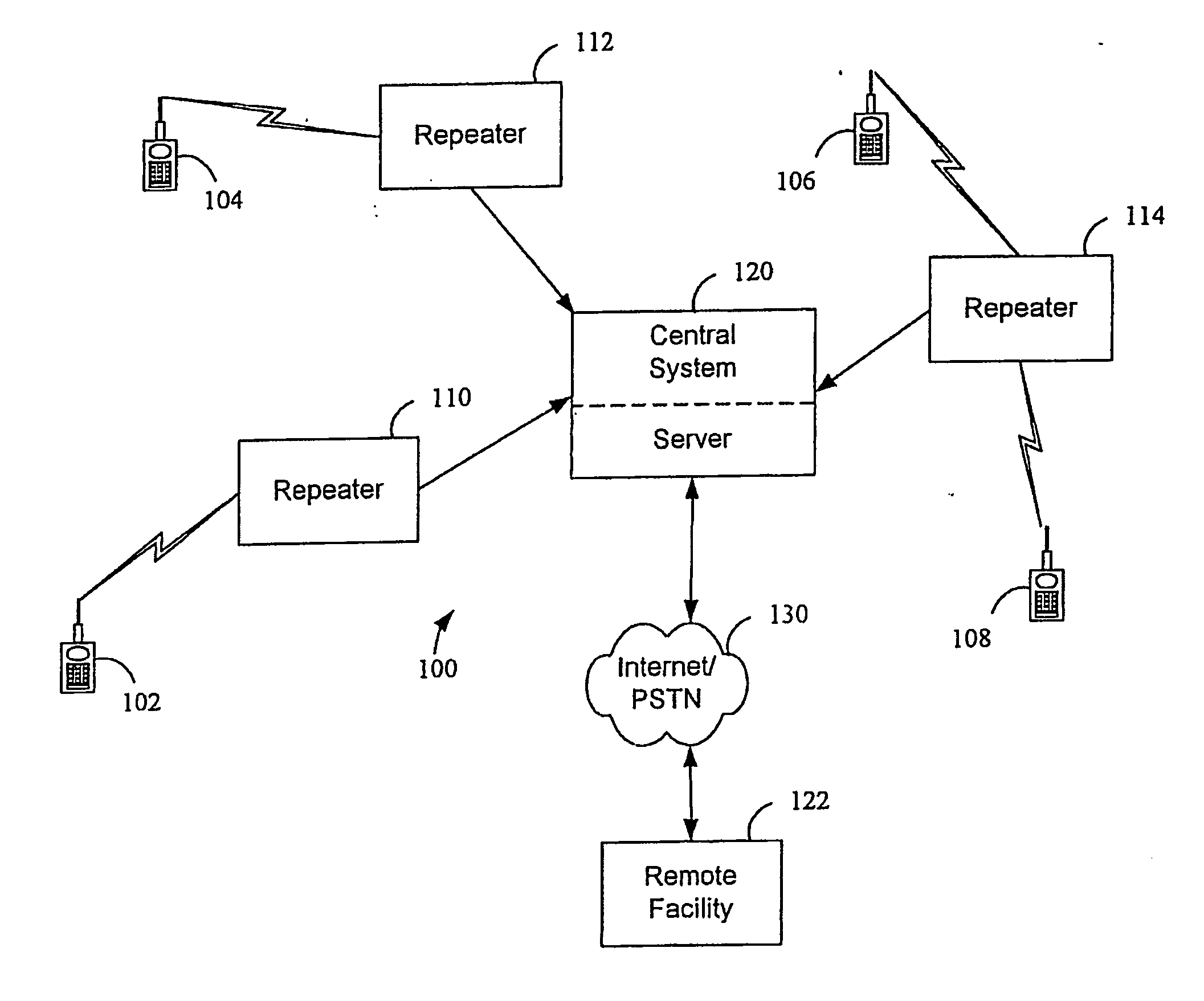
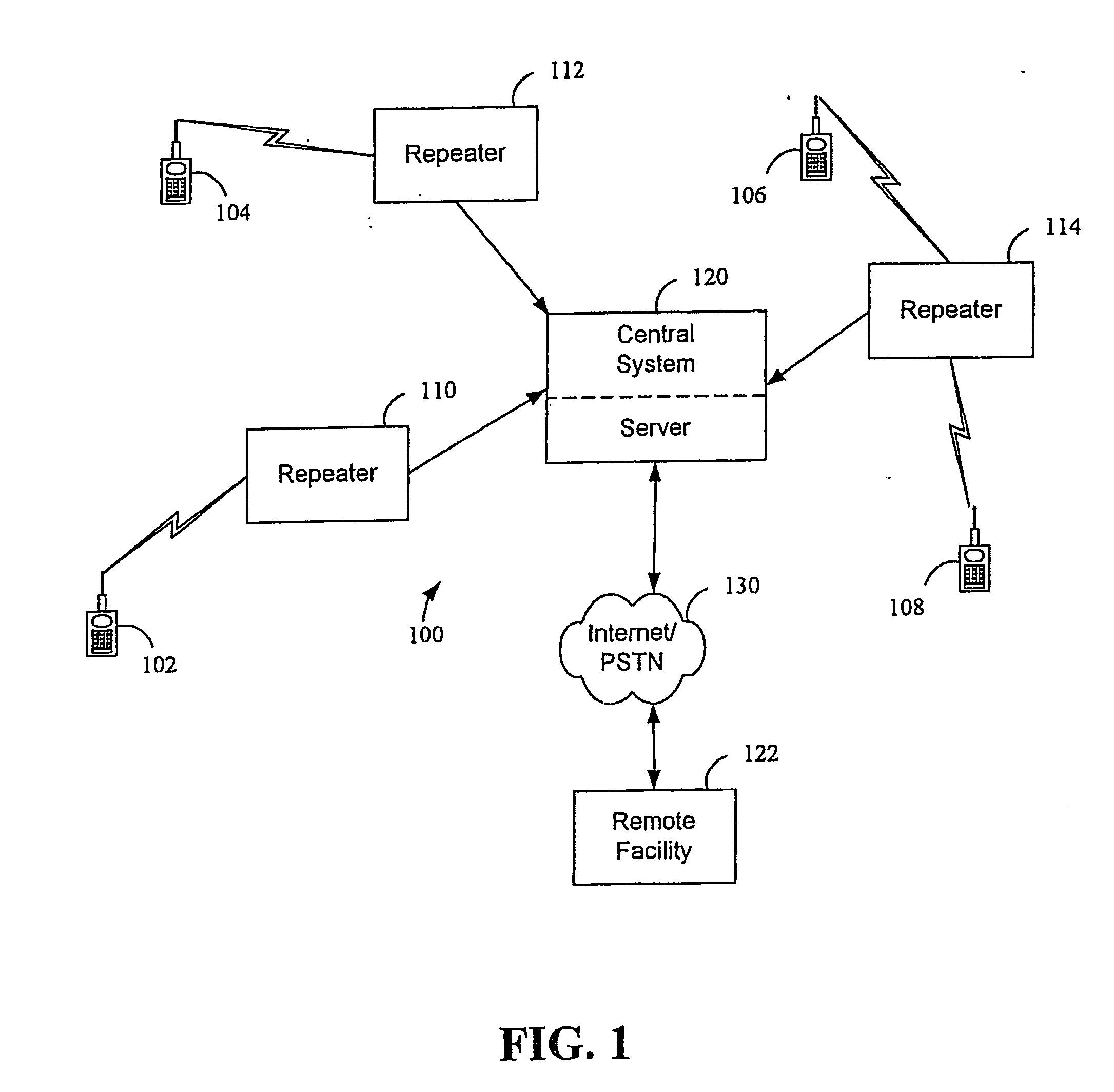
[0030] Referring now to the drawings, reference is made to FIG. 1, which is a diagram illustrating certain fundamental components of a system 100 in accordance with one preferred embodiment of the present invention. The system 100 can include a plurality of transmitters 102, 104, 106, and 108. These transmitters 102, 104, 106, and 108 are preferably RF (Radio Frequency) transmitters that are relatively small in size and transmit a relatively low power RF signal. The transmission range of a given transmitter 102, 104, 106, and 108 is preferably relatively limited in some embodiments. As will be appreciated from the description that follows, this relatively limited transmission range of the transmitters 102, 104, 106, and 108 is an advantageous and desirable characteristic of the system 100. Although the transmitters 102, 104, 106, and 108 are depicted as including a keypad, in certain embodiments of the invention the transmitters 102, 104, 106, and 108 may include many types of user ...


PUM


Abstract

Systems and methods for monitoring conditions are provided. A system can comprise a plurality of wireless transmitters and a plurality of repeaters. At least one wireless transmitter can be integrated into an alarm. The repeaters can be dispersed throughout a region at defined locations. The system can also include a computer to receive information communicated from the repeaters and the transmitters. The computer can include software for evaluating received information, identifying an alarm condition and an originating location of the alarm condition, and for reporting the alarm condition to a remote location. Other embodiments are also claimed and described.

Description

CROSS REFERENCE TO RELATED APPLICATIONS AND PRIORITY CLAIM [0001] This application is a continuation of U.S. patent application Ser. No. 09 / 704,150, filed Nov. 1, 2000, and entitled “System and Method For Monitoring and Controlling Residential Devices, now U.S. Pat. No. ______; which claims the benefit of U.S. Provisional Patent Application No. 60 / 201,252, filed May 1, 2000, and entitled “System and Method for Monitoring and Controlling Remote Devices”. This application is also a continuation-in-part of U.S. patent application Ser. No. 09 / 812,044, filed 13 Mar. 2001, and entitled “System and Method For Monitoring and Controlling Remote Devices”. U.S. patent application Ser. No. 09 / 704,150 is also a continuation-in-part of: U.S. patent application Ser. No. 09 / 271,517, filed Mar. 18, 1999, and entitled, “System For Monitoring Conditions in a Residential Living Community”, now abandoned; U.S. patent application Ser. No. 09 / 439,059, filed Nov. 12, 1999, and entitled, “System and Method ...

Claims


Application Information

Patent Timeline
Patent Type & Authority Applications(United States)
IPC IPC(8): H04L12/28
CPCH04L12/2825H04L12/2834H04W84/18H04L2012/2841H04L12/2836
Inventor PETITE, THOMAS D.
Owner HUNT TECH INC
Why Eureka
Try Eureka