
Tube-plug extracting apparatus

a technology of extracting apparatus and plugs, which is applied in the direction of liquid handling, instruments, manufacturing tools, etc., can solve the problems of apparatus not being able to remove screw plugs, the lower limit stop position of the cylinder that vertically moves the extracting arm cannot be adjusted, and the apparatus cannot remove screw plugs. achieve the effect of quick and accurate extraction of plugs

Active Publication Date: 2005-09-29
IDS CO LTD
View PDF5 Cites 17 Cited by
  • Summary
  • Abstract
  • Description
  • Claims
  • Application Information

AI Technical Summary

Benefits of technology

[0010] The object of the present invention is to provide a tube-plug extracting apparatus capable of quickly accurately extracting plugs of any of different types from test tubes of different sizes regardless of the tube size and type of plug attached to each test tube.
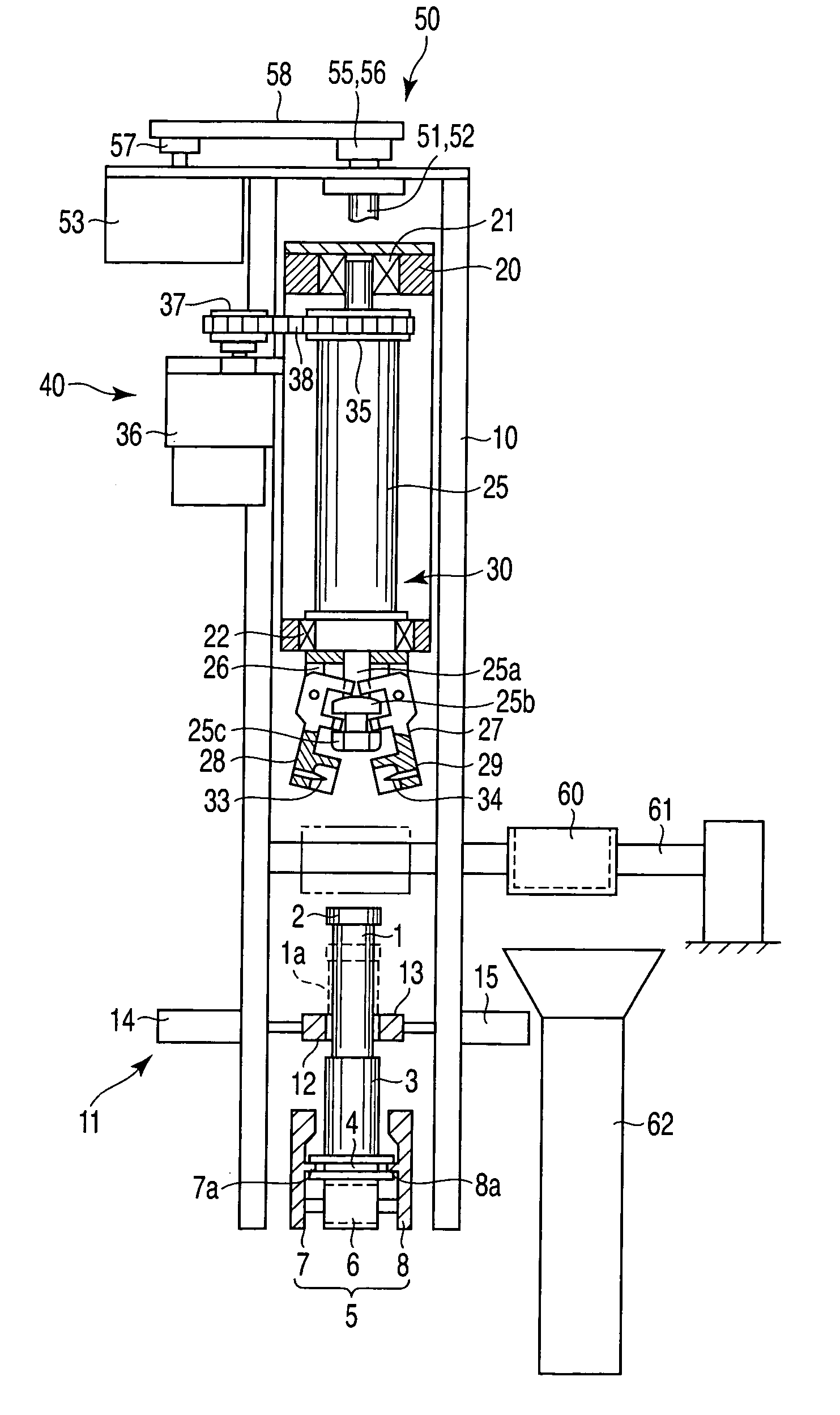
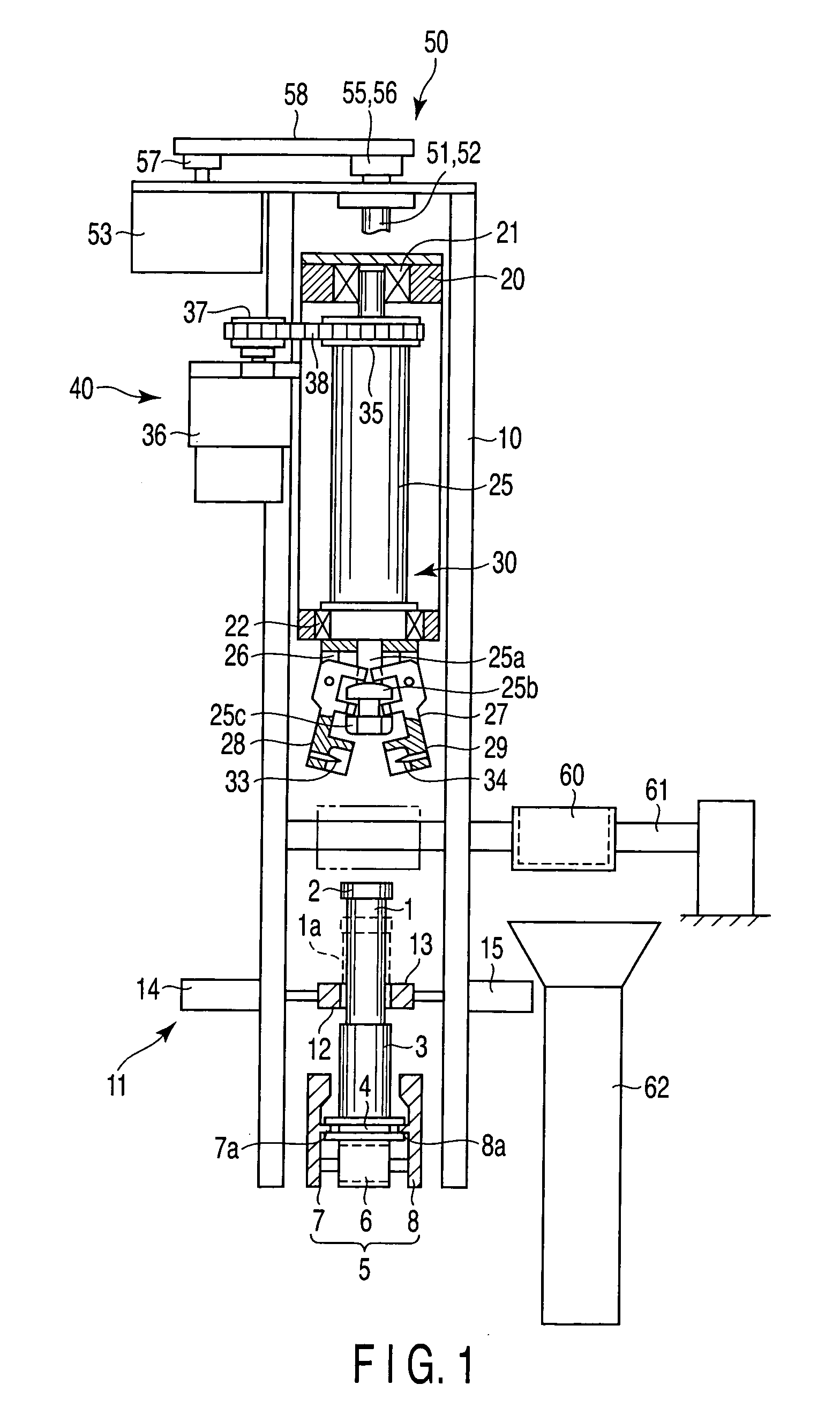
[0016] In the tube-plug extracting apparatus according to the invention, the test tube is held by the clamping mechanism, and the plug on the tube is extracted in a manner such that the chucking mechanism chucking the plug is rotated as the movable frame is raised in the direction to extract the plug. Thus, the plug can be extracted quickly and accurately from the tube regardless of to the size of the tube and type of plug attached to the tube.

Problems solved by technology

In other words, it is not provided with any means for adaptation to test tubes of different sizes or plug types.
Thus, a lower-limit stop position of the cylinder that vertically moves the extracting arm cannot be adjusted corresponding to a change of length of the test tubes.
Thus, the apparatus cannot remove a screw plug that requires several turns for its extraction.

Method used


Image

  • Tube-plug extracting apparatus
  • Tube-plug extracting apparatus
  • Tube-plug extracting apparatus

Examples


Embodiment Construction

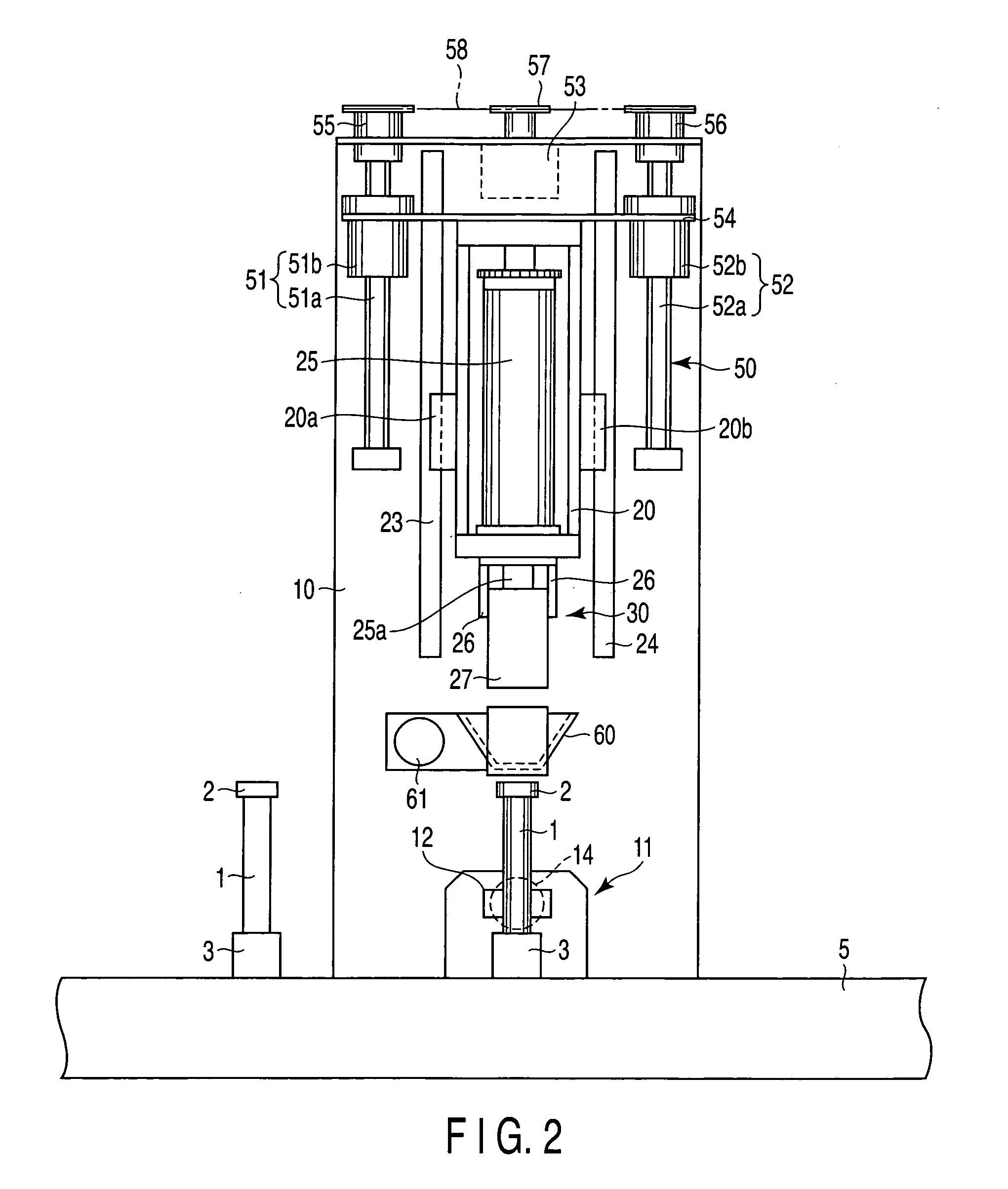
[0025] A tube-plug extracting apparatus 100 according to an embodiment of the present invention will now be described with reference to FIGS. 1 to 6. The tube-plug extracting apparatus 100 extracts a plug 2 from a plugged test tube 1. The tube-plug extracting apparatus 100 deals with a plurality of test tubes of different dimensions, represented by the large-sized test tube 1, which has a large bore and is long, and a small-sized test tube 1a which has a small bore and is short.

[0026] In FIG. 1, the large- and small-sized test tubes 1 and 1a are represented by full and broken lines, respectively, for the sake of convenience. The test tube 1 or 1a contains a blood sample. Any other sample may be put in the tube 1 or 1a. An opening portion of the tube 1 or 1a is closed by a plug 2. The tube 1 or 1a is inserted into a tube holder 3 and kept upright therein.

[0027] The lower end portion of the tube holder 3 has a pair of flanges, upper and lower. Thus, an annular groove 4 is provided b...


PUM

PropertyMeasurementUnit
sizeaaaaaaaaaa
rotationaaaaaaaaaa
lengthsaaaaaaaaaa

Abstract

A tube-plug extracting apparatus has a clamping mechanism, movable frame, chucking mechanism, rotation mechanism, and vertical motion mechanism. The clamping mechanism holds a test tube upright. The movable frame is located over a plug extracting position and slides in a vertical direction. The chucking mechanism chucks a plug attached to the test tube. The rotation mechanism rotates the chucking mechanism. The vertical motion mechanism moves the movable frame in a direction to extract the plug. The vertical motion mechanism has ball screws and a drive motor. The ball screws have a stroke long enough to move the movable frame in order to shift a lower-limit stop position for chucking the plug corresponding to the size of test tube.

Description

CROSS-REFERENCE TO RELATED APPLICATIONS [0001] This application is based upon and claims the benefit of priority from prior Japanese Patent Application No. 2004-091871, filed Mar. 26, 2004, the entire contents of which are incorporated herein by reference. BACKGROUND OF THE INVENTION [0002] 1. Field of the Invention [0003] The present invention relates to a tube-plug extracting apparatus capable of automatically extracting a plug from a test tube containing a sample, such as blood. [0004] 2. Description of the Related Art [0005] A tube-plug extracting apparatus is described and shown in Paragraph 0007 and FIG. 1 of Jpn. Pat. Appln. KOKAI Publication No. 5-228379. In this apparatus, a plug that is put into a test tube is chucked by a distal end portion of an extracting arm with the tube held by a tube retainer. The extracting apparatus is constructed so that the chucked plug can be automatically extracted from the test tube in the direction in which the plug is pulled off by raising ...

Claims


Application Information

Patent Timeline
Patent Type & Authority Applications(United States)
IPC IPC(8): B01L99/00B67B7/02G01N35/02C02F1/26C02F1/44G01N35/04
CPCB67B7/02Y10T29/53Y10T29/53443B67B7/10
Inventor ITOH, TERUAKI
Owner IDS CO LTD
Learn More