
Golf club head having face support

a golf club and support technology, applied in the field of golf clubs, can solve the problems of adversely affecting the durability of the club head, affecting the performance characteristics of the club, and arising from the stress distributed across the club head

Active Publication Date: 2005-10-27
TAYLOR MADE GOLF
View PDF23 Cites 153 Cited by
  • Summary
  • Abstract
  • Description
  • Claims
  • Application Information

AI Technical Summary

Benefits of technology

[0006] Briefly, and in general terms, the present invention provides a golf club head having enhanced durability and performance characteristics. The club head includes a face plate and a body having a face support for receiving the face plate. The body includes a top, a toe end and a heel end, a sole, and a forward wall. The forward wall defines a front opening about which the face support is disposed. The face support receives the face plate, thereby enclosing the front opening of the body.
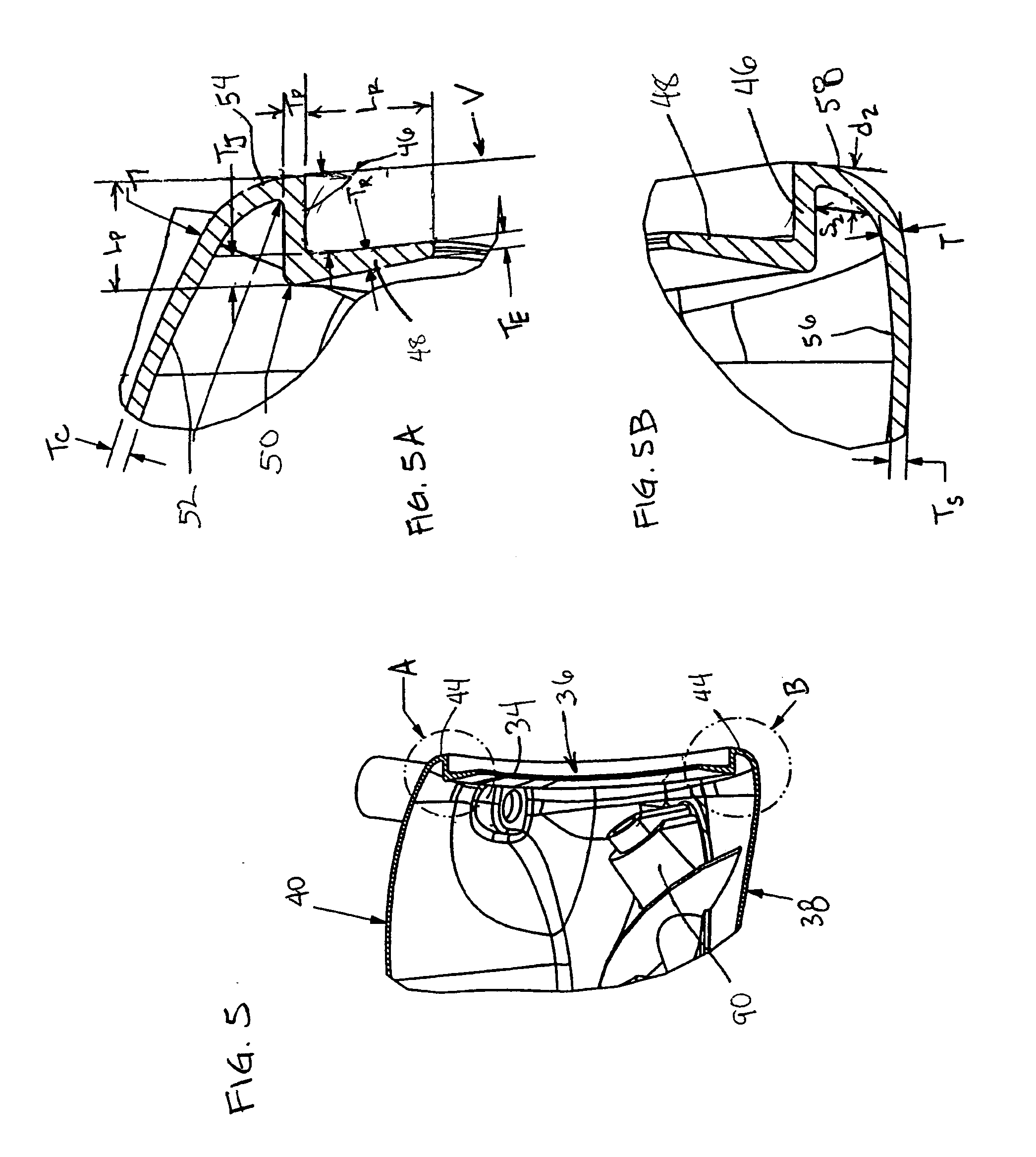
[0007] More specifically, and by way of example, the face support is configured to contribute to durability and performance characteristics of the club head. The face support includes portions proximate to the top, the toe end, and the heel end. Each of these portions includes a peripheral member extending rearward from the forward wall and a rear member extending inward from the peripheral member, with respect to the front opening. The face support can also include a portion proximate to the sole of the body. The face support contributes to increased COR even about the periphery of the face plate while providing durable support. Thus, the face plate can be designed with an emphasis on performance. For example, the face plate can be configured with a face thickness variation that provides a maximum COR over a larger face area than otherwise possible. Preferably, the face plate is formed from composite material; however, a lightweight metal face plate may alternatively be attached to a metal body of the club head. In addition, in an exemplary embodiment, a junction of the peripheral and rear members of the face support has a maximum thickness of between about 1.5 and 2 mm.

Problems solved by technology

However, overly thin walls can adversely affect the club head's durability.
Problems also arise from stresses distributed across the club head upon impact with the golf ball, particularly at junctions of club head components, such as the junction of the face plate with other club head components.
These approaches tend to affect club performance characteristics adversely, e.g., size of sweet sport, inhibiting design flexibility in both mass distribution and the face structure of the club head.
Thus, these club heads fail to provide much forgiveness to off-center hits for all but the most expert golfers.

Method used


Image

  • Golf club head having face support
  • Golf club head having face support
  • Golf club head having face support

Examples


Embodiment Construction

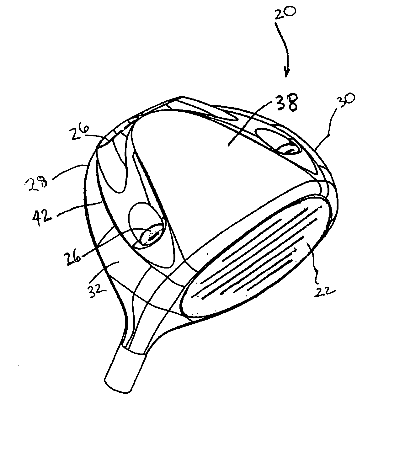
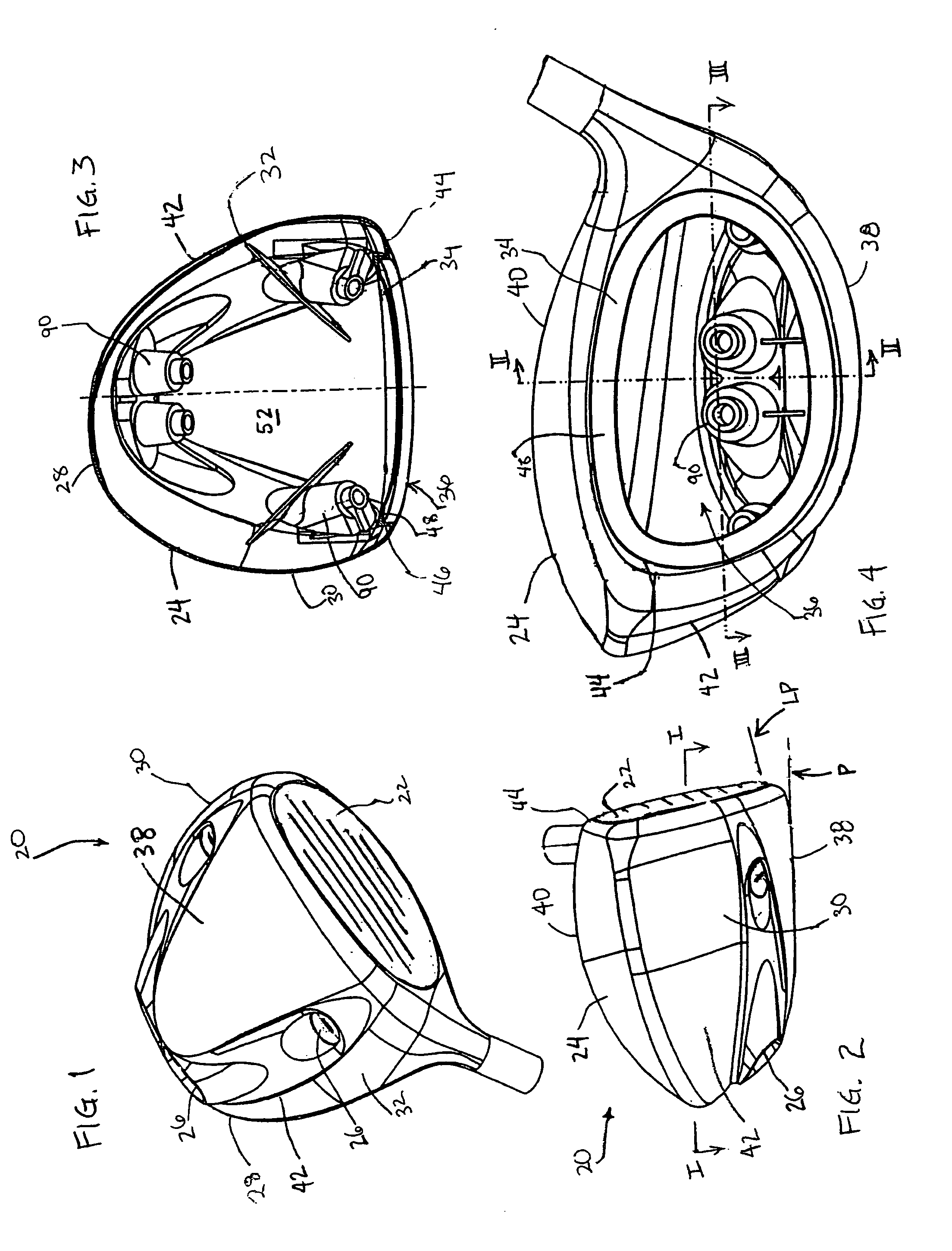
[0035] The drawings include preferred embodiments of golf club heads in accordance with the present invention. With reference to FIGS. 1-4, a wood-type club head 20 is shown having a separate face plate 22 and a body 24. The body and the face plate are relatively light, thereby facilitating the use of four removable weights 26 disposed about the periphery of the club head, including two weights in a rear region 28 of the body, one weight in a toe region 30, and one weight in a heel region 32 of the body. The body includes a face support 34 disposed about a front opening 36 of the body for receiving the face plate. The face support provides durable support while contributing to club performance, to include high COR even about the periphery of the face plate. More particularly, upon impact with a golf ball, the face support promotes defection of the face plate even about the periphery thereof.

[0036] The body 24 includes a sole 38, a top (i.e., crown 40), a skirt 42, and a forward wal...


PUM


Abstract

A golf club head has a body having a top, a sole, a toe end, a heel end, and a forward wall. The forward wall defines a front opening about which a face support is disposed. The face support receives a face plate, thereby enclosing the front opening of the body. The face support includes portions proximate to the top, the toe end, and the heel end, each portion having a peripheral member extending rearward from the forward wall and a rear member extending inward from the peripheral member, with respect to the front opening. The face support can be combined with a preferred face construction and weight elements to optimize club head performance to help a golfer achieve greater distance and control.

Description

BACKGROUND OF THE INVENTION [0001] The present invention relates generally to golf clubs and, more particularly, to an improved golf club head having face support. [0002] Many factors must be considered when designing a golf club head. One factor is the distribution of mass about the club head, which is typically quantified by parameters for moments of inertia and center of gravity. Moments of inertia of a club head are measures of a club head's resistance to angular acceleration and are related to the distribution of mass from reference axes. It is desirable for a club head to have high moments of inertia, particularly to promote forgiveness for off-center hits. To achieve high moments of inertia, designers typically position mass to the periphery of the golf club head and backwards from the face plate. In addition, a club head's center of gravity is spaced from the face plate at a prescribed location to achieve a desired launch angle upon impact with a golf ball. As a result, for ...

Claims


Application Information

Patent Timeline
IPC IPC(8): A63B53/04A63B53/06
CPCA63B53/0466A63B53/047A63B53/06A63B2053/0408A63B2053/0412A63B2053/042A63B2053/0491A63B2053/0425A63B2209/023A63B2053/0433A63B2053/0416A63B60/00A63B53/0408A63B53/0412A63B53/0416A63B53/042A63B53/0425A63B53/0433
Inventor CHAO, BING-LINGWEED, BRIANLARSEN, PETERZIMMERMAN, GERYVINCENT, BENOIT
Owner TAYLOR MADE GOLF
Learn More