Peripherals of computer

Active Publication Date: 2005-10-27
OKI ELECTRIC IND CO LTD
View PDF6 Cites 16 Cited by
  • Summary
  • Abstract
  • Description
  • Claims
  • Application Information

AI Technical Summary

Benefits of technology

[0033] According to the invention, by notifying the upper apparatus of the device descriptor showing either the function information indicative of the functions of the peripheral or the function information indicative of the functions of the dependent peripheral which is USB-connected to the peripheral on the basis of the selecting instruction, the upper apparatus specifies the communication partner destination on the basis of the single function information since only one function information is shown in the device descriptor. Thus, the dedicated driver to issue the switching command of the connecting construction is unnecessary in the upper apparatus and troublesomeness to install the dedicated driver into the PC can be eliminated.

Problems solved by technology

In the conventional system, however, since the dedicated driver for selecting the desired function from the plurality of functions and issuing the switching command of the connecting construction is needed and it is necessary to develop such a dedicated driver and install it into the PC as mentioned above, they cause a problem.

Method used


Image

  • Peripherals of computer
  • Peripherals of computer
  • Peripherals of computer

Examples


embodiment 1

[Embodiment 1]

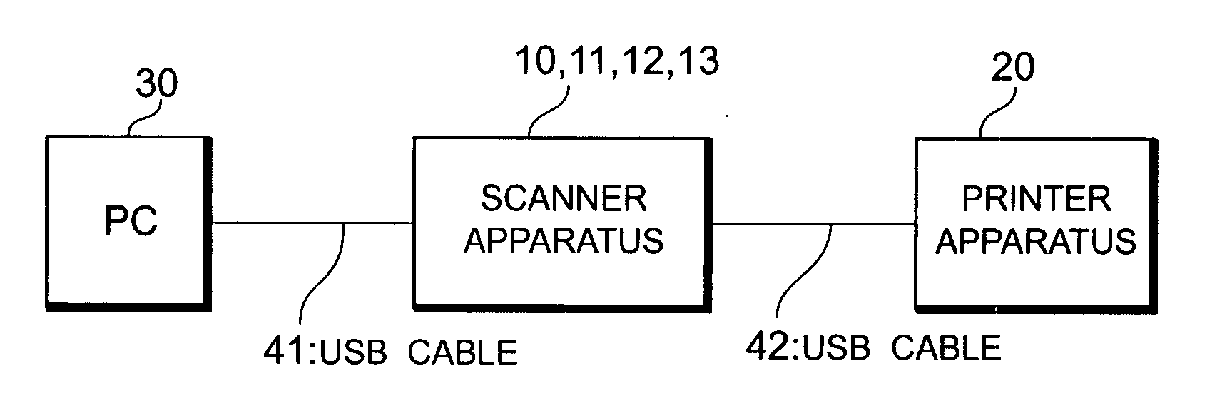
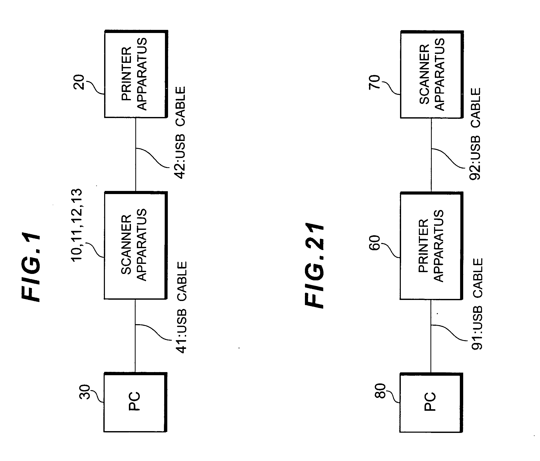
[0065] An image reading apparatus as a peripheral of the invention is a scanner apparatus 10. As shown in FIG. 1, the scanner apparatus 10 is connected to a PC 30 as an upper apparatus through a USB cable 41 and further connected to an image forming apparatus (printer apparatus 20) as a dependent peripheral through a USB cable 42.

[0066] An essence of the invention will now be described.

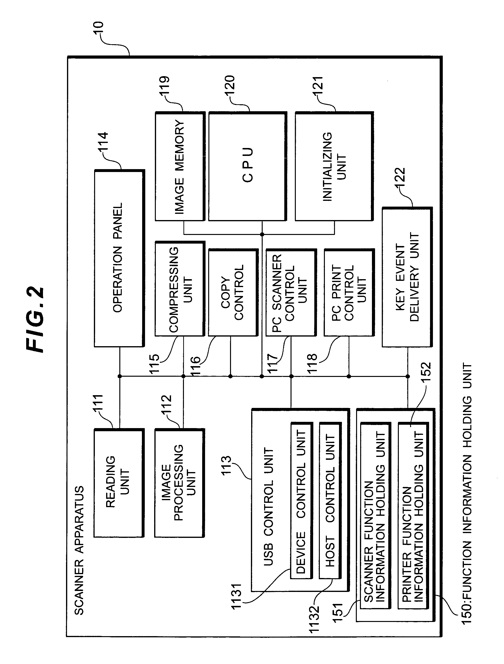
[0067] In the scanner apparatus 10 of the invention, as shown in FIG. 2, function information indicative of functions of the scanner apparatus 10 and function information indicative of functions of the printer apparatus 20 which is USB-connected to the scanner apparatus have previously been held in a function information holding unit 150. On the basis of a selecting instruction, the scanner apparatus 10 reads out only one of the function information held in the function information holding unit 150. A device descriptor in which the read-out function information is shown is formed by a ...

embodiment 2

[Embodiment 2]

[0111] Since a system construction of the embodiment 2 is similar to that of the embodiment 1 shown in FIG. 1, its explanation is omitted here.

[0112] As shown in FIG. 12, according to a scanner apparatus 11 in the embodiment 2, the functions of the construction of the scanner apparatus 10 in the embodiment 1 are changed and new functions are added. Specifically speaking, the construction of the scanner apparatus 11 in the embodiment 2 differs from that of the embodiment 1 with respect to the following component elements: a reading unit 111′ for reading the original; a USB control unit 113A; an original detection event delivery unit 123 for, when it is detected that the original has been put in the reading unit, transmitting information indicative of the detection to the device control unit 1131 of the USB control unit 113A; a left-original detecting timer 124 for detecting that the state where the original has been put in the reading unit continued for a predetermined...

embodiment 3

[Embodiment 3]

[0125] Since a system construction of the embodiment 3 is similar to that of the embodiment 1 shown in FIG. 1, its explanation is omitted here.

[0126] As shown in FIG. 14, according to a scanner apparatus 12 in the embodiment 3, the following component elements are added to the construction of the scanner apparatus 11 in the embodiment 2: a USB control unit 113B in place of the USB control unit 113A; a PC print control unit 118′ for making control for the PC printer; and a printer simple emulation event delivery unit 126 for transmitting information indicative of detection of a command to switch the device descriptor from the printer descriptor to the scanner descriptor to the USB control unit 113B.

[0127] The PC print control unit 118′ has a printer simple emulation unit (specific information extracting unit) 1181 for analyzing the printer language sent from the PC 30 and detecting the “command to switch the device descriptor from the printer descriptor to the scanner...


PUM


Abstract

A peripheral for notifying a USB-connected upper apparatus of a device descriptor and allowing the upper apparatus to specify a communication partner destination by the function information shown in the device descriptor has: a peripheral function information holding unit which holds function information showing functions of the peripheral; a dependent peripheral function information holding unit which holds function information showing functions of a USB-connected dependent peripheral; and a USB control unit which reads out one of the function information held in those holding units by a selecting instruction and notifies the upper apparatus of the device descriptor in which the read-out function information is shown. A peripheral which can realize a multi-function without developing a dedicated driver and installing it into a PC is provided.

Description

BACKGROUND OF THE INVENTION [0001] 1. Field of the Invention [0002] The invention relates to peripherals which are connected to an upper apparatus through a USB (Universal Serial Bus) interface and, more particularly, to peripherals for realizing multi-function. [0003] 2. Related Background Art [0004] An upper apparatus (hereinafter, referred to as a PC (personal computer)) having a USB-connecting function can be connected and disconnected to / from peripherals in the state where the PC operates (state where a power source is ON) and, further, can be connected in parallel to a plurality of peripherals. Therefore, since the USB-connection is easily detachable and a system can be relatively freely constructed, the USB-connection has been widespread. The peripheral added by the USB-connection is recognized by the PC at the moment when it is physically connected to the PC. The PC which recognized the peripheral searches for a driver of the recognized peripheral from drivers which it alrea...

Claims


Application Information

Patent Timeline
Patent Type & Authority Applications(United States)
IPC IPC(8): H04N1/00
CPCH04N1/00236H04N1/00241H04N2201/0081H04N2201/0044H04N2201/0049H04N1/00278
Inventor WATANABE, YUICHI
Owner OKI ELECTRIC IND CO LTD
Why Eureka
Try Eureka