Rotary extendable hair clipper

a hair clipper and extension technology, applied in the field of hair clippers, can solve the problems of accumulating fatigue of the operator's wrist or fingers, affecting the operation of the hair clipper, and requiring a relative large manipulation force,

Inactive Publication Date: 2005-11-10
EPILADY 2000 LLC
View PDF28 Cites 49 Cited by
  • Summary
  • Abstract
  • Description
  • Claims
  • Application Information

AI Technical Summary

Benefits of technology

[0011] An aspect of the present invention provides a hair cutting apparatus, comprising a chassis to support a motor to drive a cutting blade, a rotary ring, including an inner circumferential surface, rotatably mounted on said chassis,a threaded screw having a head including an outer circumferential surface to engage with the inner circumferential surface of the rotary ring, and a shaft including threads, the threaded screw rotating in response to the rotation of the rotary ring, a longitudinal positioner having threads to engage with said threads of the threaded screw, to move in a longitudinal direction relative to the chassis in accordance with the rotation of the threaded screw and a hair engagement comb coupled with said longitudinal positioner to position hair to be cut by the cutting blade.

Problems solved by technology

However, since the movable blade in conventional devices is urged against the stationary blade by a torsion spring to provide a suitable spring bias to cause a hair shearing reciprocating motion of the movable blade on the stationary blade, a relatively large manipulation force is required to slide the adjuster handle and therefore the movable blade against a friction between the blades when adjusting the cut length of the hairs.
This is inconvenient and is therefore a cause of accumulating fatigue of a wrist or fingers of the operator when shearing the hairs while varying the cut length continuously and manually.
Additionally, it may be expected that such linkage member and latch means create difficulties because of necessary complex structures.
However, since the cutting blade is moved relative to the stationary blade, the ability to cut hair at any particular length is limited to the distance between the stationary blade from the housing, which is predetermined at the time of manufacture and which is necessarily relatively short relative to desired hair lengths for many people.
Further, since the hair-cutting blade is moved relative to the body of the device, the blade may be damaged during the course of the lifetime of the blade, resulting in lowered reliability and cutting efficiency.

Method used


Image

  • Rotary extendable hair clipper
  • Rotary extendable hair clipper
  • Rotary extendable hair clipper

Examples


Embodiment Construction

[0028] Reference will now be made in detail to the present embodiments of the present invention, examples of which are illustrated in the accompanying drawings, wherein like reference numerals refer to the like elements throughout. The embodiments are described below in order to explain the present invention by referring to the figures.

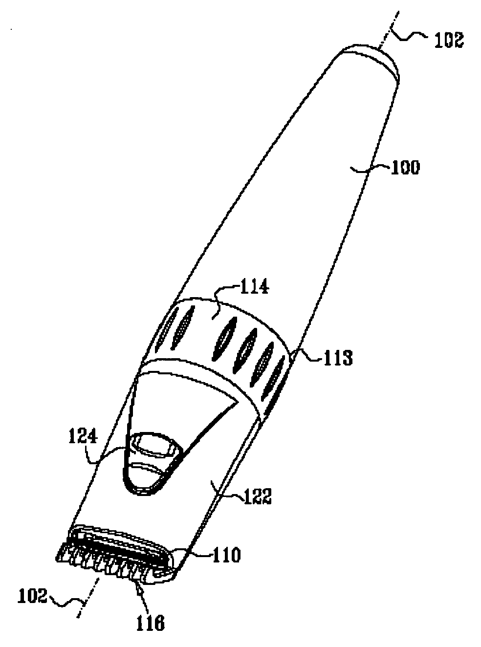
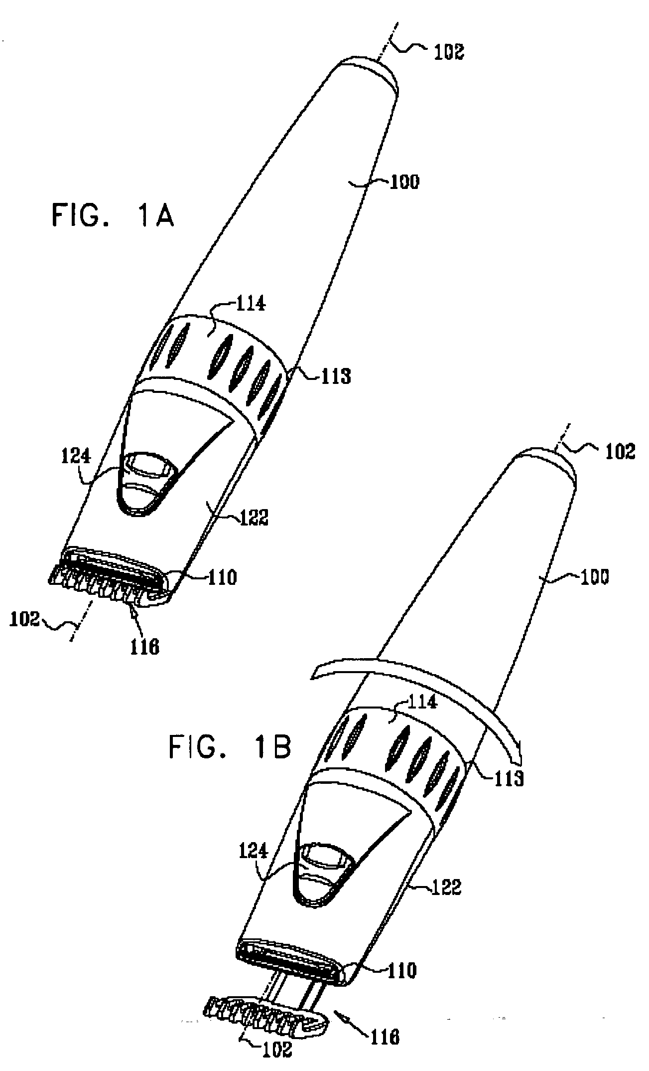
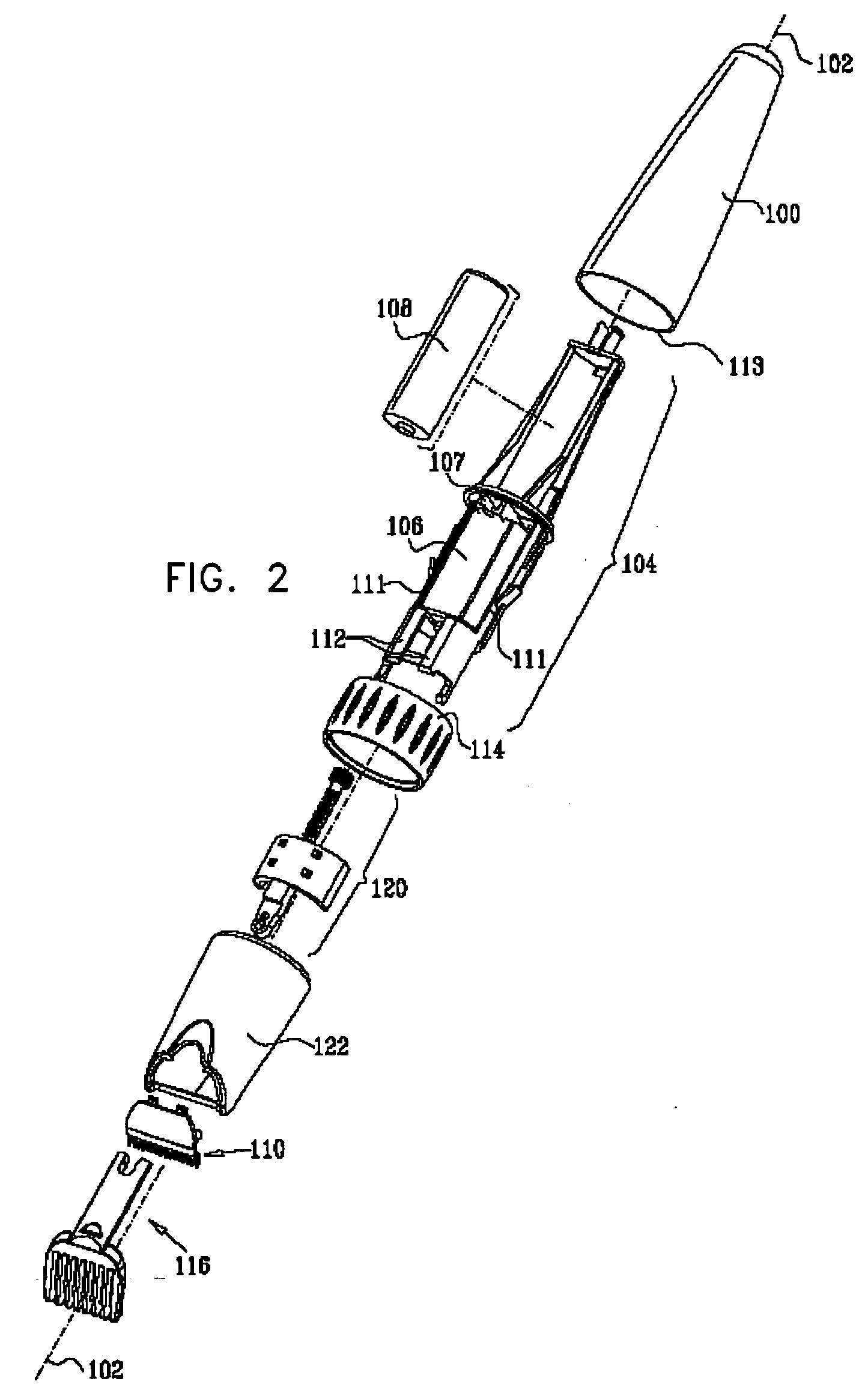
[0029] Reference is now made to FIGS. 1A and 1B, which are pictorial illustrations of an extendable hair-clipping device constructed and operative in accordance with an embodiment of the present invention in a retracted orientation and an extended orientation respectively and to FIG. 2 which is an exploded view illustration of the hair-clipping device of FIGS. 1A and 1B.

[0030] As seen in FIGS. 1A, 1B and 2, the hair-clipping device comprises a generally conical rear housing portion 100 that is arranged about a longitudinal axis 102. The rear housing portion 100 partially encloses a main chassis 104. The main chassis 104 supports a motor 106, a screw...


PUM


Abstract

A hair cutting apparatus, including a chassis to support a motor to drive a cutting blade, the apparatus comprising a rotary ring, including an inner circumferential surface, rotatably mounted on said chassis, a threaded screw, constrained within said chassis against non-rotational movement, having a head including an outer circumferential surface to engage with the inner circumferential surface of the rotary ring and a shaft including threads, the threaded screw rotating in response to the rotation of the rotary ring, a longitudinal positioner, having a socket including threads to engage with said threads of the threaded screw, to move in a longitudinal direction relative to the cutting blade in accordance with the rotation of the threaded screw, and a hair engagement comb coupled with said longitudinal positioner to position hair to be cut by the cutting blade.

Description

CROSS REFERENCE TO RELATED APPLICATION [0001] This application is based on related Israeli Application No. 160955, filed Mar. 18, 2004, in the Israeli Intellectual Property Office, the disclosure of which is incorporated herein by reference. BACKGROUND OF THE INVENTION [0002] 1. Field of the Invention [0003] The present invention relates to hair clippers generally, and, more particularly, to a hair cutting apparatus, including an extendable hair engagement comb. [0004] 2. Description of the Related Art [0005] Conventional hair clippers with varying cut length capability have been well known for some time. Generally, these included devices in which a movable blade is moved relative to a stationary blade for varying a cut length of hairs by moving an adjuster handle mounted on a housing of the hair clipper in a direction along the longitudinal axis of the housing. The movable blade is interlocked with the adjuster handle through a linkage member in such a manner that the movable blade...

Claims


Application Information

Patent Timeline
Patent Type & Authority Applications(United States)
IPC IPC(8): A45DB26B19/00B26B19/20
CPCB26B19/20
Inventor PORAN, YEHUDA
Owner EPILADY 2000 LLC
Why Eureka
Try Eureka