Controlled artificial intervertebral disc implant

a technology of intervertebral discs and implants, which is applied in the field of intervertebral disc replacement, can solve the problems of destabilization of the functional spinal unit, reduced physiologic range of motion, severe discomfort, etc., and achieves the effects of reducing particle generation, reducing wear, and reducing discomfor

Active Publication Date: 2005-11-10
SYNTHES USA
View PDF99 Cites 455 Cited by
  • Summary
  • Abstract
  • Description
  • Claims
  • Application Information

AI Technical Summary

Benefits of technology

[0023] The upper and lower endplates are preferably formed of metal, such as titanium, stainless steel, titanium alloys, cobalt-chromium alloys, or amorphous alloys. Alternatively, however, the upper and lower endplates may be formed of ceramics, composites, polymers, such as poly-ether-ether-ketone (i.e., PEEK) or an ultra high molecular weight polyethylene (i.e., UHMWPE), bone, including cortical, cancellous, allograft, autograft, xenograft, demineralized or partially demineralized bone, or any other materials able to serve as load bearing supports. The materials chosen for the endplates, in combination with the desired fluid, are preferably selected to reduce the amount of wear, and thus increase the life of the joint.
[0024] The outer surface of the upper and lower endplates may be substantially flat, wedge-shaped, etc. The outer surfaces of the upper and lower endplates may also be dome shaped with their radii defined in the sagittal and coronal planes to generally match those of the ends of the adjacent vertebra. The dome shape allows the upper and lower endplates to better conform with the ends of the adjacent vertebrae for a better fit in situ.
[0028] The upper and lower endplates may also preferably include articulating surfaces, thus providing the intervertebral disc with greater mobility. The articulating surfaces preferably including a surface polish or similar wear reducing finish such as diamond finish, TiNi finish, etc. in order to minimize wear, decrease particle generation, and increase disc life.
[0029] In some embodiments, the interior of the disc may include a leaf spring attached on one end to the upper and / or lower endplate but unattached on the other end. Disposed between the ends, the leaf spring preferably includes an enlarged convex intermediate section which mates, articulates, and slides with the inner surface of one of the endplates. Preferably, the unattached end of the leaf spring is attached to a roller by means of an axle, the axle allowing the roller to freely rotate thus permitting the leaf spring to move freely during the flexing of the spring.

Problems solved by technology

A variety of conditions such as spondylolysis, disc herniation, compression of spinal cord nerve roots, degenerative disc disease, and trauma are known to cause severe discomfort, requiring medical attention.
Although intervertebral and posterolateral fusion are widely used, drawbacks to their use include a reduced physiologic range of motion and other fusion related complications such as degeneration of adjacent discs and destabilization of the functional spinal unit.
Although the evolution of spinal arthroplasty and the use of prosthetics in the spine has been similar to that of other joints in the body, evolving from fusing the joint to replacing the functional joint, the advent of spinal athroplasty, however, has been slower than arthroplasty in other major joints in the body.
A few of the possible reasons why spinal arthroplasty has been delayed are that spinal problems related to disc degeneration are difficult to diagnose, spinal procedures are typically crisis-driven and thus conservative solutions such as fusion are acceptable, and spinal anatomy is complex.
For example, in the early 1960's, implants using silicone ball bearings were implanted into the cervical regions of patients, but the outcomes were uncertain.
The results of the procedure were initially promising but over time the disc spaces lost height due to subsidence of the steel balls into the vertebral bodies.
While each of the foregoing prostheses addresses some of the problems relating to intervertebral disc replacement, each of the implants presents significant drawbacks.

Method used


Image

  • Controlled artificial intervertebral disc implant
  • Controlled artificial intervertebral disc implant
  • Controlled artificial intervertebral disc implant

Examples


Embodiment Construction

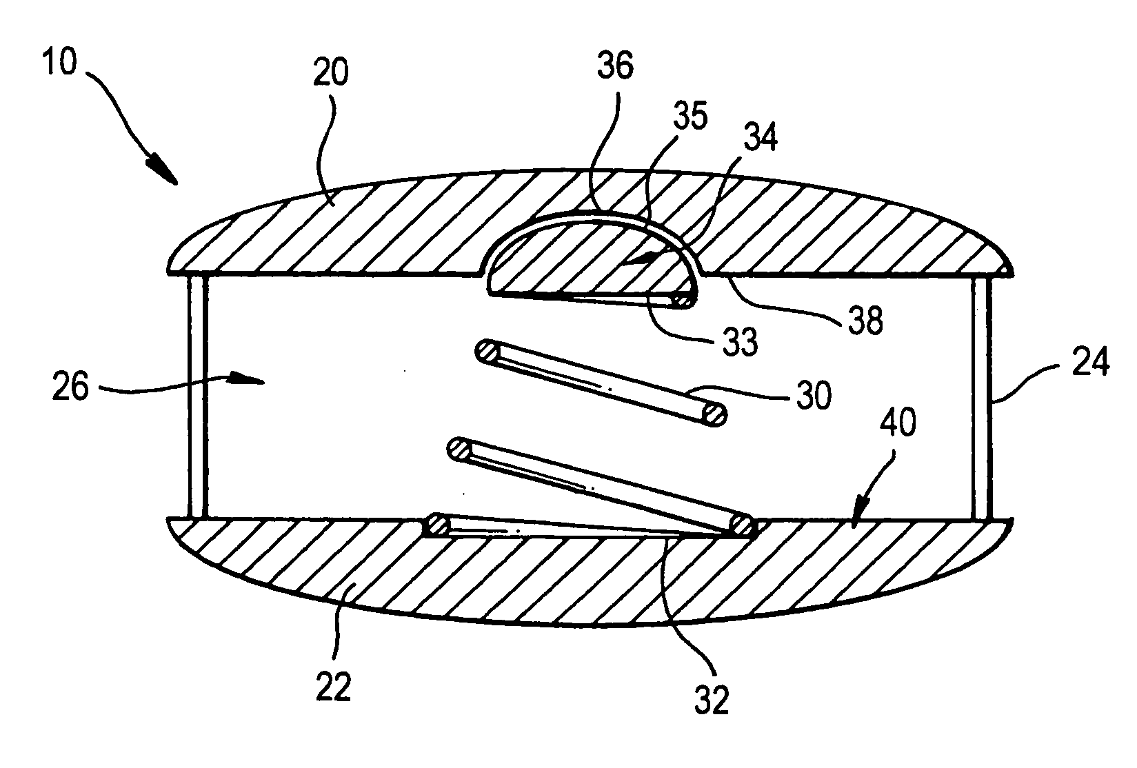
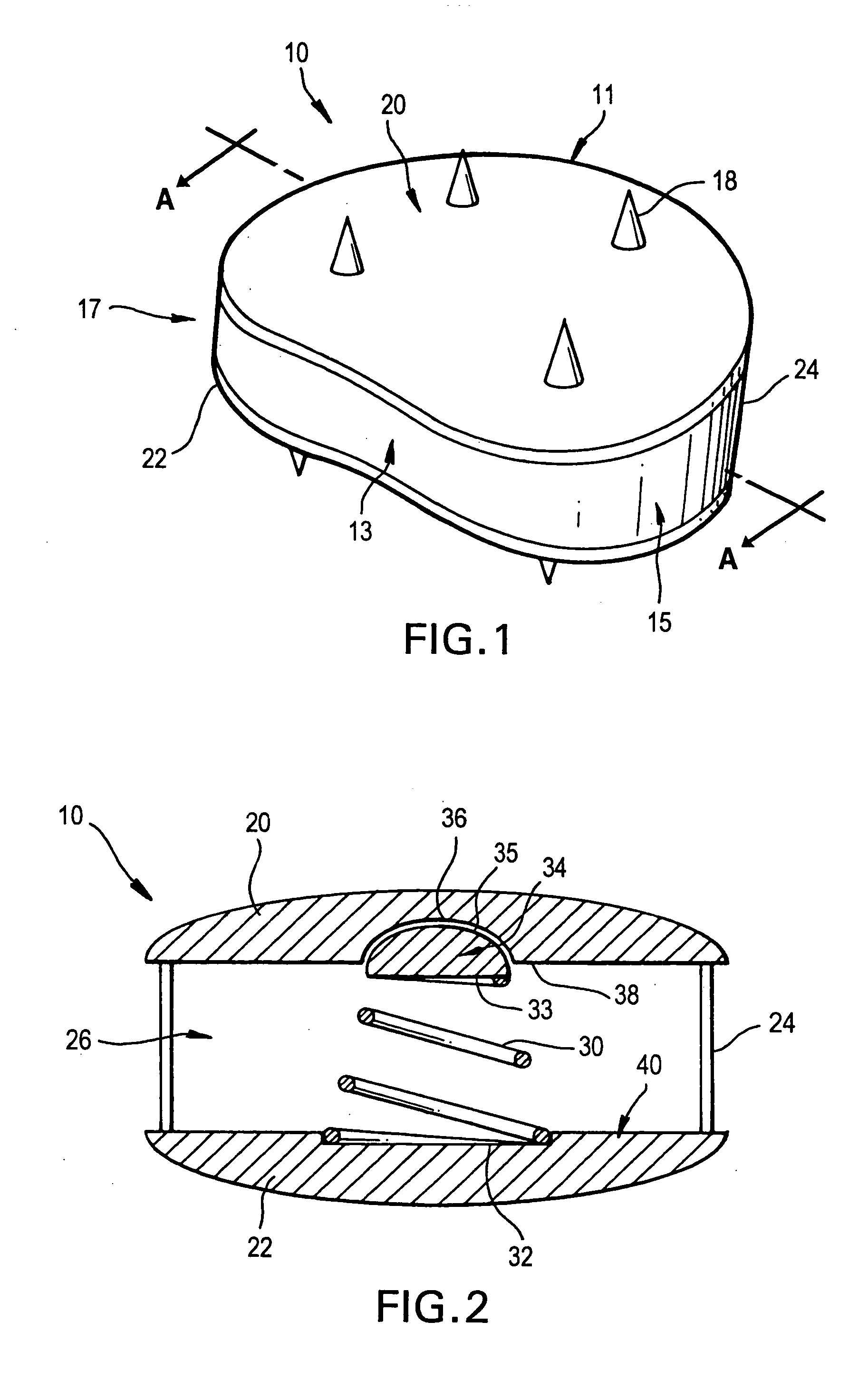
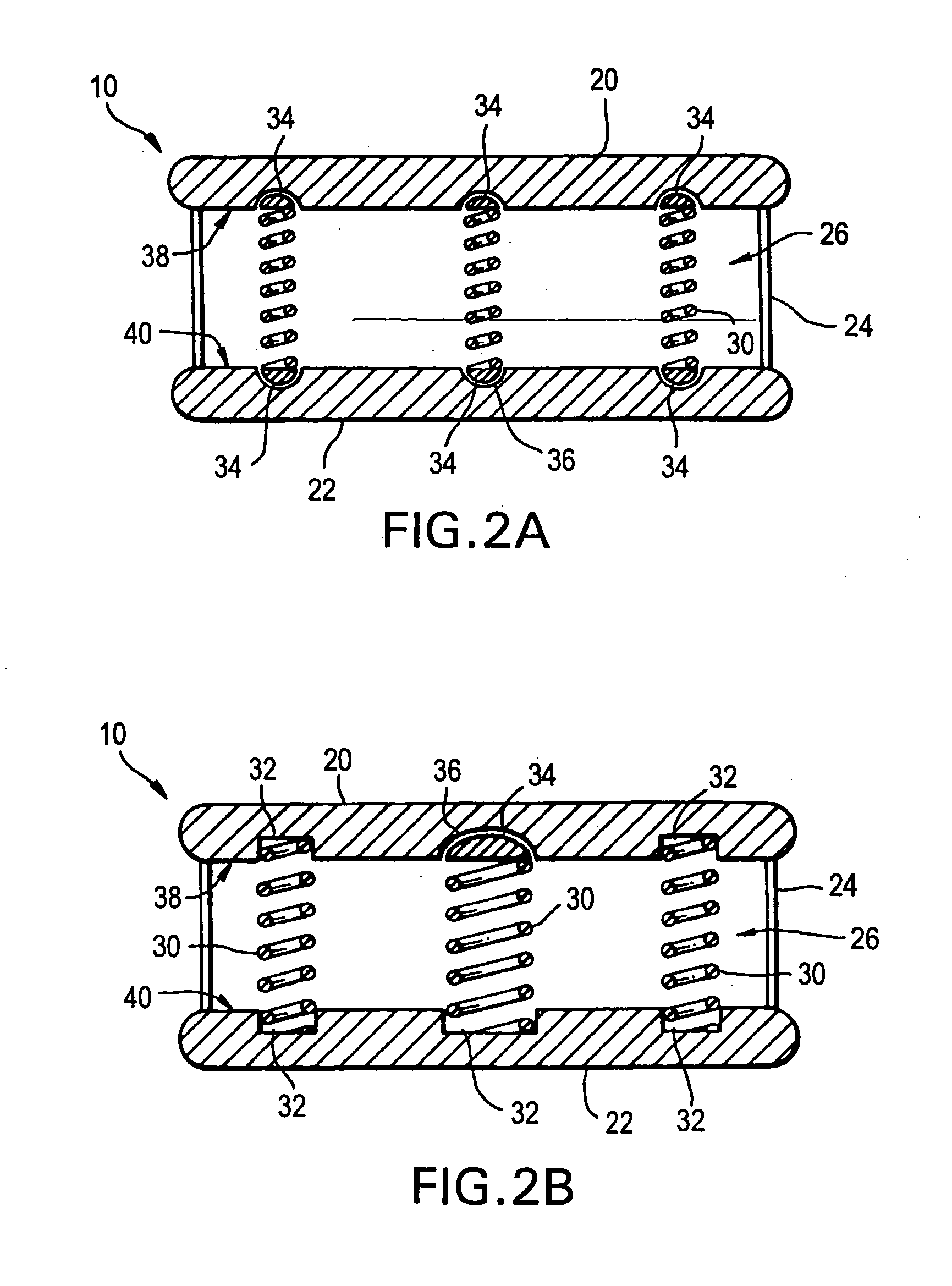
[0056] Any of a wide variety of different implant structures can be prepared according to the teachings shown by the illustrative examples of the intervertebral discs disclosed herein. The intervertebral discs of the present invention are preferably designed to restore the natural spinal curvature (or sagittal balance), disc height, to allow for a natural range of motion, absorb shock and to provide resistance to motion and axial compression.

[0057] The intervertebral discs preferably are sized and adapted for use in the cervical, thoracic, and lumbar regions of the spine. Also, the intervertebral discs can be tailored for each individual patient allowing for disc characteristics appropriate for the individual patient. For example, and artificial disc may be provided having a pair of endplates and a core, and the core of the disc can include different assemblies, different components, and / or various types of materials to create the desired dynamic characteristics for each individual...


PUM

PropertyMeasurementUnit
outer diameteraaaaaaaaaa
heightsaaaaaaaaaa
heightaaaaaaaaaa

Abstract

The invention relates to an artificial intervertebral disc for placement between adjacent vertebrae. The artificial intervertebral disc is preferably designed to restore disc height and natural disc curvature, allow for a natural range of motion, absorb shock and provide resistance to motion and axial compression. Furthermore, the intervertebral disc may be used in the cervical, the thoracic, or the lumbar regions of the spine. The artificial intervertebral disc may include either singularly or in combination: an interior including at least one spring member preferably incorporating a arcuate surface member, a flexible core, the flexible core preferably being a slotted core, a ring spring, a winged leaf spring, or a leaf spring, or The articulating member preferably being attached to one of the endplate by an intermediate shock absorbing element.

Description

CROSS REFERENCE TO RELATED APPLICATION [0001] The present application is a continuation of International Patent Application PCT / US03 / 25536 filed Aug. 15, 2003, which claims priority from U.S. Application No. 60 / 403,356 filed on Aug. 15, 2002 and U.S. Application No. 60 / 403,402 filed on Aug. 15, 2002, the entire contents of which are expressly incorporated herein by reference thereto.FIELD OF THE INVENTION [0002] The invention is related to devices and methods for the treatment of trauma and diseases of the spine. More particularly, the invention relates to intervertebral disc replacement. BACKGROUND OF THE INVENTION [0003] A variety of conditions such as spondylolysis, disc herniation, compression of spinal cord nerve roots, degenerative disc disease, and trauma are known to cause severe discomfort, requiring medical attention. Among the procedures currently used to alleviate such conditions are spinal fusion, such as intervertebral and posterolateral fusion or arthrodesis. In these...

Claims


Application Information

Patent Timeline
Patent Type & Authority Applications(United States)
IPC IPC(8): A61F2/00A61F2/08A61F2/28A61F2/30A61F2/40A61F2/44A61F2/46
CPCA61F2230/0008A61F2230/0013A61F2230/0015A61F2230/0034A61F2230/0065A61F2250/0014A61F2250/0018A61F2250/0037A61F2250/0097A61F2310/00017A61F2310/00023A61F2310/00029A61F2310/00179A61F2310/00407A61F2310/00461A61F2310/0058A61F2310/00796A61F2310/0088A61F2/08A61F2/28A61F2/30742A61F2/30767A61F2/30965A61F2/441A61F2/4425A61F2/4455A61F2/4611A61F2002/2835A61F2002/30004A61F2002/30014A61F2002/30092A61F2002/30115A61F2002/30125A61F2002/30131A61F2002/30133A61F2002/30187A61F2002/302A61F2002/30326A61F2002/30329A61F2002/30369A61F2002/30377A61F2002/30433A61F2002/30448A61F2002/30451A61F2002/30457A61F2002/30462A61F2002/30472A61F2002/30481A61F2002/30495A61F2002/3055A61F2002/30563A61F2002/30565A61F2002/30566A61F2002/30568A61F2002/30571A61F2002/30578A61F2002/30579A61F2002/30581A61F2002/30583A61F2002/30584A61F2002/30586A61F2002/30594A61F2002/30604A61F2002/30617A61F2002/30649A61F2002/3065A61F2002/30673A61F2002/30685A61F2002/30772A61F2002/30823A61F2002/30828A61F2002/30838A61F2002/30841A61F2002/30879A61F2002/30904A61F2002/30909A61F2002/30917A61F2002/3092A61F2002/3097A61F2002/4011A61F2002/443A61F2002/4629A61F2002/4631A61F2210/0014A61F2210/0085A61F2220/0025A61F2220/0033A61F2220/0041A61F2220/005A61F2220/0058A61F2220/0075A61F2230/0006A61F2310/00359A61F2002/30367
Inventor GERBER, DAVIDCOPPES, JUSTIN K.ANGELUCCI, CHRISTOPHERPAUL, DAVID C.STIHL, PASCALBOYER, MICHAEL L.
Owner SYNTHES USA
Why Eureka
Try Eureka