Method of automatically flushing debris from an electrically-operated hydraulic valve

a technology of electrically operated hydraulic valves and automatic flushing, which is applied in the direction of valve operating means/releasing devices, mechanical equipment, transportation and packaging, etc., can solve the problems of preventing proper valve operation, accumulating debris between the armature and the valve seat, and fine debris normally present in filtered hydraulic transmission fluid

Inactive Publication Date: 2005-11-17
GM GLOBAL TECH OPERATIONS LLC
View PDF5 Cites 151 Cited by
  • Summary
  • Abstract
  • Description
  • Claims
  • Application Information

AI Technical Summary

Benefits of technology

[0004] The present invention is directed to an improved method of operation for an electrically-activated hydraulic valve of a motor vehicle transmission, where a normal activation of the valve is overridden to automatically and periodically open an armature of the valve to flush out debris that has accumulated between the armature and a seat that the armature is designed to engage. In a preferred implementation, the electrically-activated valve and a pressure regulator valve develop fluid pressure for maintaining engagement of one or more hydraulically-activated torque transmitting devices (i.e., clutches), and maximum clutch pressure is produced when the armature engages the seat. When excessive slippage of a clutch is detected, the armature is forced into engagement with the seat until the slippage is reduced or a predetermined period of time has elapsed, after which the armature is temporarily positioned away from the seat to provide full flow of hydraulic fluid across the seat to flush out debris that prevents the armature from engaging the seat. During Neutral operation of the transmission, the armature is continuously positioned away from the seat to provide full flow of hydraulic fluid across the seat for keeping the seat free of debris, and during low torque and speed operating conditions of the transmission, the armature is periodically positioned away from the seat for a predetermined interval to provide full flow of hydraulic fluid across the seat to flush out any accumulated debris.

Problems solved by technology

It has been found that very fine debris normally present in filtered hydraulic transmission fluid can accumulate in the boost valve and prevent proper valve operation.
In particular, the debris can accumulate between the armature and the valve seat under conditions where the armature is positioned very close the seat.
The accumulation of debris then prevents the armature from engaging the seat when conditions so require, causing the produced boost pressure, and therefore the clutch pressure, to deviate from the desired value.
Depending on the design of the valve, the erroneous clutch pressure can result in clutch slippage and other harmful consequences.

Method used


Image

  • Method of automatically flushing debris from an electrically-operated hydraulic valve
  • Method of automatically flushing debris from an electrically-operated hydraulic valve
  • Method of automatically flushing debris from an electrically-operated hydraulic valve

Examples


Embodiment Construction

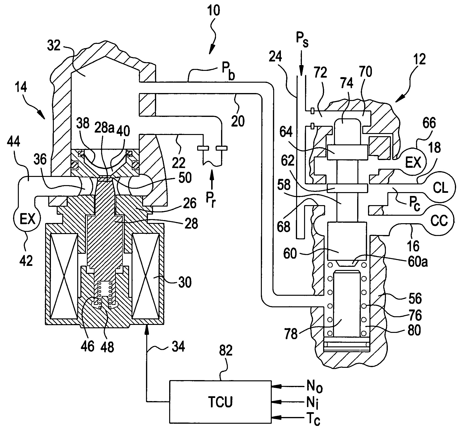
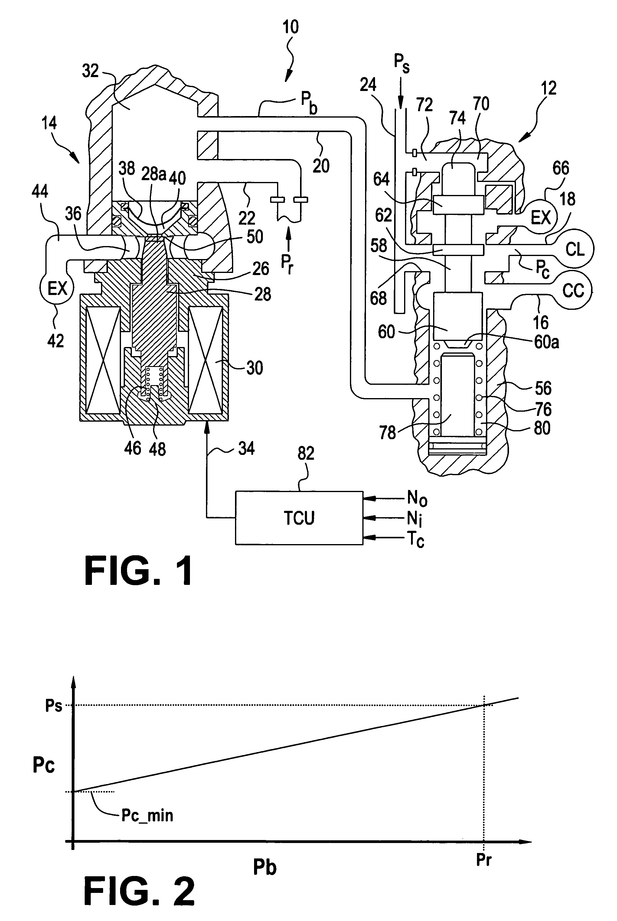
[0009] Referring to FIG. 1, the reference numeral 10 generally designates a hydraulic pressure regulation circuit of a motor vehicle transmission, including a hydraulically-activated pressure regulator valve (PRV) 12 and an electrically-activated boost pressure valve (BPV) 14. The PRV 12 supplies hydraulic fluid to a cooler circuit (CC) via line 16 and regulates a clutch pressure (Pc) in line 18 for at least one hydraulically-engaged clutch CL. The BPV 14 supplies a boost pressure Pb to PRV 12 via line 20. The boost pressure Pb is derived from a reference pressure Pr supplied to BPV 14 via flow restricted line 22, while the cooler circuit fluid and clutch pressure Pc are derived from a pump supply pressure Ps in line 24. Of course, the PRV 12 and BPV 14 may be combined into a single valve if desired.

[0010] The BPV 14 includes a valve body 26, an armature 28, a solenoid coil 30 and a valve chamber 32 to which lines 20 and 22 are coupled. The solenoid coil 30 is electrically activate...


PUM


Abstract

The normal control of an electrically-activated hydraulic valve armature is overridden to automatically and periodically open the armature for flushing out debris that has accumulated between the armature and a seat that the armature is designed to engage. The valve develops fluid pressure for maintaining engagement of a motor vehicle transmission clutch, and when excessive slippage of the clutch is detected, the armature is forced into engagement with the seat until the slippage is reduced or a predetermined period of time has elapsed, after which the armature is temporarily positioned away from the seat to provide full flow of hydraulic fluid across the seat to flush out debris that prevents the armature from engaging the seat. During Neutral operation of the transmission, the armature is continuously positioned away from the seat, and during low torque conditions the armature is temporarily positioned away from the seat.

Description

TECHNICAL FIELD [0001] The present invention is related to the control of an electrically-activated hydraulic valve for regulating fluid pressure in a motor vehicle transmission, and more particularly to a method of preventing erroneous operation of the valve due to accumulation of debris. BACKGROUND OF THE INVENTION [0002] In motor vehicle transmissions having hydraulically-engaged clutches (or other friction devices), it is desirable to regulate the clutch pressure to a value that is sufficient to prevent clutch slippage without being unnecessarily high. This can be achieved with a hydraulic circuit including a hydraulic pressure regulator valve and an electrically-operated boost valve that supplies a bias or boost pressure to the regulator valve. The relationship between the boost pressure and the clutch pressure can be established by a way of a look-up table, for example, and once the desired clutch pressure is known, the transmission controller can use the look-up table to dete...

Claims


Application Information

Patent Timeline
Patent Type & Authority Applications(United States)
IPC IPC(8): F15B21/041F15B21/08F16H61/12F16K29/00F16K31/02F16K31/42
CPCF01L2001/34436F15B21/041F15B21/087Y10T477/6936Y10S477/906Y10T477/6934Y10T477/75F16K31/426Y10T137/043
Inventor FOSTER, MICHAEL D.HSIEH, TUNG-MINGHUBBARD, GREGORY A.
Owner GM GLOBAL TECH OPERATIONS LLC
Why Eureka
Try Eureka