Sensors and associated methods for controlling a vacuum cleaner

a technology of vacuum cleaner and sensor, which is applied in the direction of cleaning equipment, electric equipment installation, instruments, etc., can solve the problems that technology and innovation are both limiting factors in the capability of household cleaning robots

Active Publication Date: 2005-12-22
ROYAL APPLIANCE MFG
View PDF17 Cites 130 Cited by
  • Summary
  • Abstract
  • Description
  • Claims
  • Application Information

AI Technical Summary

Benefits of technology

[0008] In one aspect of the invention, a cleaning appliance includes a housing with a brushroll and a wheel mounted thereto. A floor-type sensor is disposed within a mounting tube secured to the housing. The floor-type sensor emits sonic energy toward a surface being traversed by the cleaning appliance and receives corresponding sonic energy reflected by the surface. A comparator, electrically coupled to the floor-type sensor, compares the received reflected sonic energy to one or more associated predetermined values to determine the type of surface being traversed. A processor analyzes the results of the comparison and controls at least one of a suction fan, said wheel and said brushroll, based at least in part on the analysis.
[0009] In another aspect of the invention, a vacuum cleaner has a housing that includes: a suction opening located in a bottom wall of the housing; a brushroll mounted to the housing and located in the suction opening; a wheel mounted to the housing for supporting the housing on a subjacent surface; and a mounting tube secured to the housing, wherein the mounting tube includes a first end, opening to the housing bottom wall; and a second end. A floor type sensor is disposed adjacent to the mounting tube second end and emits sonic energy toward the subjacent surface and receives corresponding sonic energy reflected by the surface. A comparator, electrically coupled to the sensor, compares the received reflected sonic energy to one or more associated predetermined values to determine the type of surface being traversed. A processor analyzes the results of the comparison and controls at least one of a suction fan, the wheel and the brushroll, based at least in part on the analysis.
[0010] In still another aspect of the invention, a vacuum cleaner includes a floor nozzle with a suction opening communicating with a suction source; a brushroll; a first motor for driving said brushroll; at least one wheel on which said floor nozzle is mounted to allow the floor nozzle to move in relation to a subjacent surface; a second motor for driving said at least one wheel; and a mounting tube including a first end, opening toward the subjacent surface, and a second end. A sonic sensor disposed adjacent to the mounting tube second end emits sonic energy toward the subjacent surface and receives corresponding sonic energy reflected by the surface. A comparator, electrically coupled to the sensor, compares the received reflected sonic energy to one or more associated predetermined values to determine the type of surface being traversed. A processor analyzes the results of the comparison and controls at least one of the suction source, the first motor, and the second motor.

Problems solved by technology

Currently, technology and innovation are both limiting factors in the capability of household cleaning robots.

Method used


Image

  • Sensors and associated methods for controlling a vacuum cleaner
  • Sensors and associated methods for controlling a vacuum cleaner
  • Sensors and associated methods for controlling a vacuum cleaner

Examples


Embodiment Construction

[0032] While the invention is described in conjunction with the accompanying drawings, the drawings are for purposes of illustrating exemplary embodiments of the invention and are not to be construed as limiting the invention to such embodiments. It is understood that the invention may take form in various components and arrangement of components and in various steps and arrangement of steps beyond those provided in the drawings and associated description. Within the drawings, like reference numerals denote like elements. It is to be appreciated that the invention is amenable to various applications. For example, a traditional upright vacuum cleaner, a traditional canister vacuum cleaner, a carpet extractor, other types of vacuum cleaners, and other types of robotic vacuums. More generally, this invention is amenable to various types of household appliances, both indoor, such as floor polishers, and outdoor, such as lawnmowers or window washing robots.

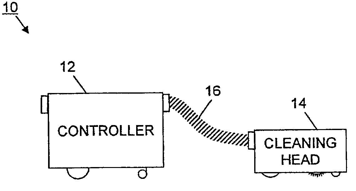
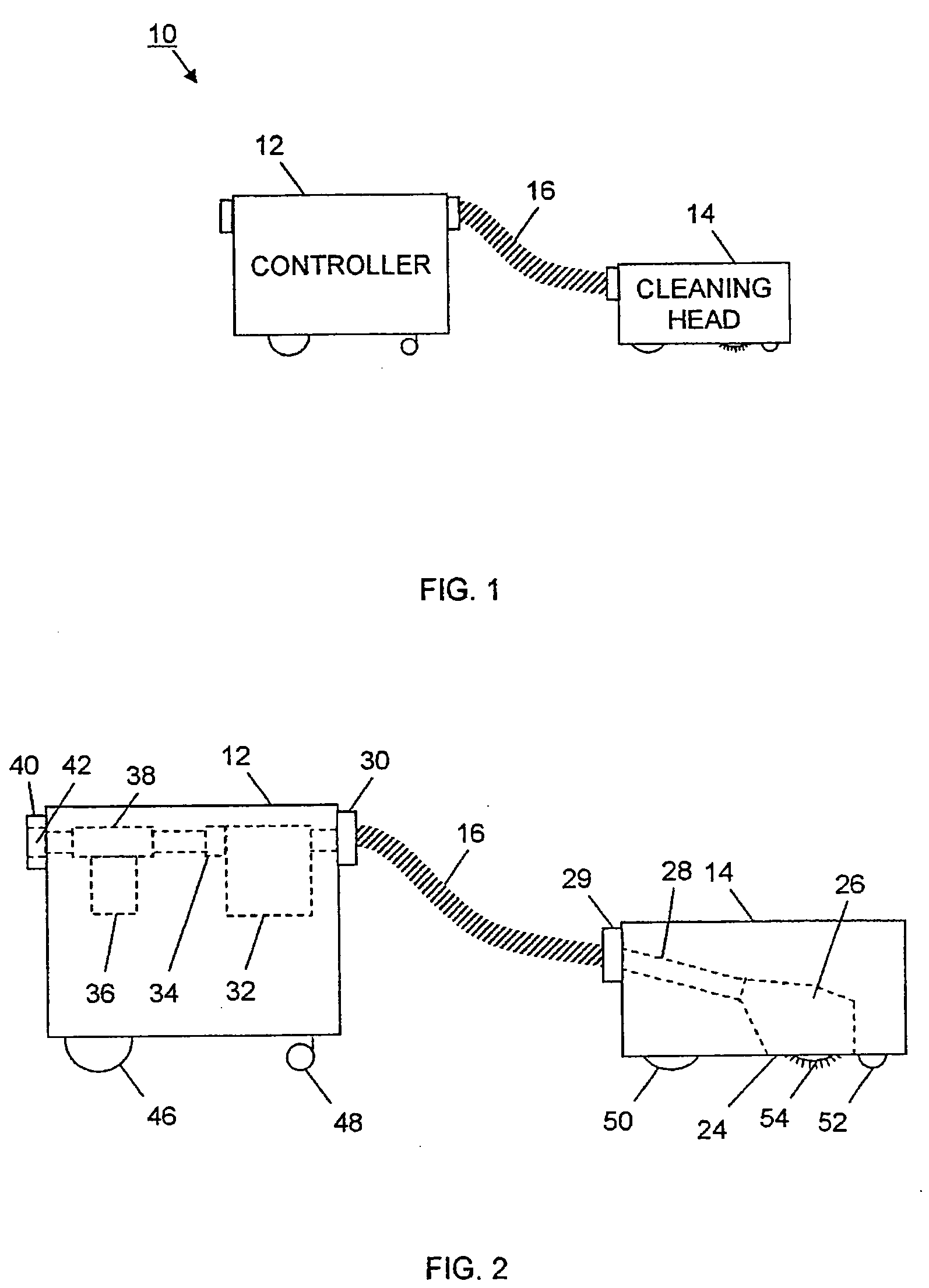
[0033] With reference to FIG. ...


PUM


Abstract

A cleaning appliance includes a housing with a brushroll and a wheel mounted thereto. A floor-type sensor is disposed within a mounting tube secured to the housing. The floor-type sensor emits sonic energy toward a surface being traversed by the cleaning appliance and receives corresponding sonic energy reflected by the surface. A comparator, electrically coupled to the floor-type sensor, compares the received reflected sonic energy to one or more associated predetermined values to determine the type of surface being traversed. A processor analyzes the results of the comparison and controls at least one of a suction fan, said wheel and said brushroll, based at least in part on the analysis.

Description

CROSS-REFERENCE TO RELATED PATENTS AND APPLICATIONS [0001] This application is a Continuation-In-Part of US Utility Patent Application serial No. 10 / 665,709 filed on Sep. 19, 2003 and entitled “SENSORS AND ASSOCIATED METHODS FOR CONTROLLING A VACUUM CLEANER,” the entirety of which is incorporated herein by reference.BACKGROUND OF INVENTION [0002] The invention relates to methods of controlling a vacuum cleaner using various types of sensors. It finds particular application in conjunction with upright vacuum cleaners as well as robotic vacuum cleaners. A suitable robotic vacuum cleaner includes, but is not limited to, a controller, a cleaning head, and an interconnecting hose assembly, and the invention will be described with particular reference thereto. However, it is to be appreciated that the invention is also amenable to other applications. For example, a traditional upright vacuum cleaner, a traditional canister vacuum cleaner, a carpet extractor, other types of vacuum cleaners...

Claims


Application Information

Patent Timeline
Patent Type & Authority Applications(United States)
IPC IPC(8): A47L5/00A47L9/00A47L9/28G06F7/00
CPCA47L9/2821A47L9/2842A47L9/2889A47L9/2852A47L9/2857A47L9/2847A47L9/2805A47L9/2826A47L9/2831
Inventor REINDLE, MARK E.SIEGEL, NORMAN
Owner ROYAL APPLIANCE MFG
Why Eureka
Try Eureka