Thin keypad assemblies and components for electronics devices and methods

Active Publication Date: 2005-12-22
MOTOROLA MOBILITY LLC
View PDF16 Cites 52 Cited by
  • Summary
  • Abstract
  • Description
  • Claims
  • Application Information

AI Technical Summary

Problems solved by technology

In the past, keypads on cellular radiotelephones device have comprised a multi-layered structure having a large pa

Method used


Image

  • Thin keypad assemblies and components for electronics devices and methods
  • Thin keypad assemblies and components for electronics devices and methods
  • Thin keypad assemblies and components for electronics devices and methods

Examples


Embodiment Construction

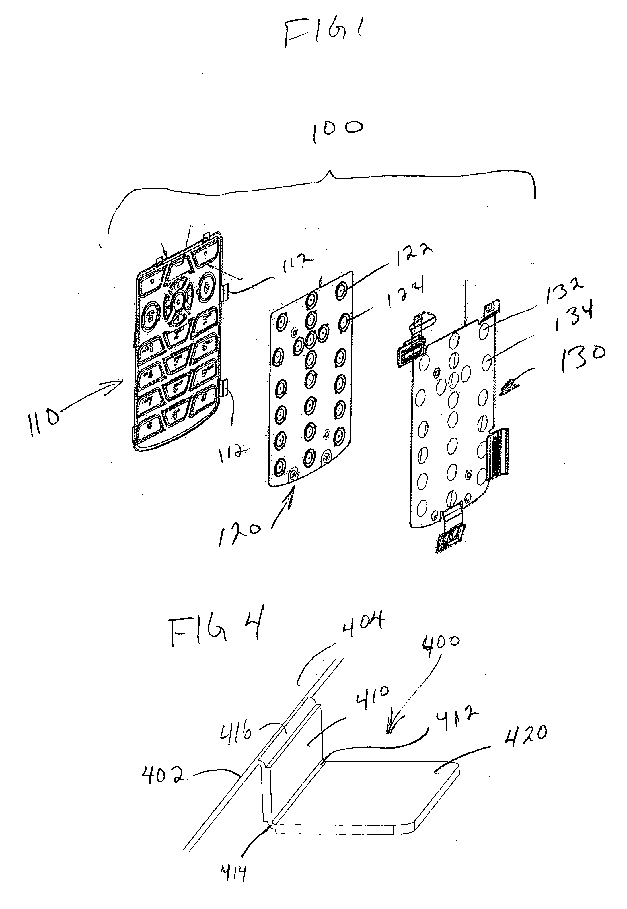
[0014]FIG. 1 illustrates an exploded view of an exemplary keypad assembly 100 comprising generally a user interface keycap layer assembly 110, a switch-dome / luminescent layer assembly 120 and a keypad circuitry layer 130. The exemplary keypad assembly 100 and variations thereof, which will become more apparent from the discussion below, have applications in handheld electronics devices, for example, calculators, personal organizers, personal digital assistants, wired and wireless communications devices including cellular telephones, portable computing machines, among other devices.

[0015] The exemplary key cap assembly layer 110 comprises generally a key cap layer having a plurality of user interface key caps flexibly coupled to a carrier or carrier portions. FIG. 5 illustrates an exemplary key cap layer 510. In one embodiment, each key cap is flexibly coupled to the carrier along at least one side of the key cap, and other remaining sides of the key cap are separated from other key...


PUM


Abstract

A keypad assembly, the keypad assembly including a keycap layer 110 having multiple user interface key caps flexibly coupled to a carrier portion, a luminescent layer 120 disposed toward a backside of the plurality of key cap layer, the luminescent layer carrying a plurality of switch domes aligned with a corresponding one of the plurality of key caps of the key cap layer. In some embodiments, a backing material is applied to a backside of the user interface keycaps.

Description

FIELD OF THE DISCLOSURE [0001] The present disclosure relates generally to input devices, and more particularly to keypad assemblies and keypad components, for example, keypad assemblies and components for use in super-thin applications, for example, wireless communications devices, and corresponding methods. BACKGROUND OF THE DISCLOSURE [0002] In the past, keypads on cellular radiotelephones device have comprised a multi-layered structure having a large part count that is relatively thick, thus limiting in the thinness of the devices in which the keypad is integrated. Typical keypads include user interface forming user accessible key caps, which are sometimes interconnected by a web. The key caps are each aligned over a corresponding switch-dome mounted on a carrier made of Mylar or some other carrier material. The carrier and dome assembly is disposed on a switch contact circuitry layer. [0003] To provide keypad lighting, it is known to dispose a luminescent layer between the dome...

Claims


Application Information

Patent Timeline
IPC IPC(8): B41J5/08H01H13/702H04M1/23
CPCH01H13/702H01H2209/07H04M1/23H01H2221/004H01H2221/002H01H13/705H01H13/704H01H13/70
Inventor DOMBROWSKI, RICHARD J.GORDECKI, RYSZARD J.RODGERS, DANIEL P.CAUWELS, PATRICK J.EMMERT, STEVE C.
Owner MOTOROLA MOBILITY LLC
Why Eureka
Try Eureka