Apparatus for dental diagnosis and treatment

a technology for dental diagnosis and treatment, applied in the field of improvement of dental diagnosis and treatment apparatus, can solve the problems of inability to use, eye fatigue becomes outrageous, and the type of treatment is performed with great difficulty

Inactive Publication Date: 2006-01-05
FUJIE HIDEHIRO +1
View PDF9 Cites 28 Cited by
  • Summary
  • Abstract
  • Description
  • Claims
  • Application Information

AI Technical Summary

Problems solved by technology

Therefore, the treatment of such an accuracy level with the naked eyes is an operation on the verge of the limit of discriminating power of the eye, and hence fatigue of the eyes becomes outrageous.
However, since it is a site which is difficult to be seen with the naked eyes, this type of treatment is performed with great difficulty.
Even when an attempt is made to carry out the treatment while shooting pictures by the intraoral camera, since both hands of the dentist's are already occupied, he / she can use it only for the purpose of inspecting the state of the tooth surface but cannot use it for the purpose of performing the treatment.
There are some problems in the method of proceeding treatment while looking at the site to be treated with the dental mirror.
In this method, the dental mirror is subject to fog up from breath of the patient.
In addition, when grinding the tooth, splashing water ejected from the grinding tool may attach on the dental mirror and hinder the reflection of the dental mirror, which results in great difficulty in treatment.
Therefore, a large majority of dentists cannot proceed the treatment while mirroring the site to be treated and looking at the image in the dental mirror, but use the dental mirror only for inspecting the state of the site to be treated before and after the treatment.
Therefore, when the dentist moves his / her right hand 46A while looking at this image, the hand moves in the direction opposite from the intended direction vertically and laterally, and hence it is hardly possible to carry out treatment in this state.
Therefore, there arises a problem in that the intraoral camera is moved by being pushed by the tongue or the lip.
However, in this apparatus, although the monitor for displaying the image can be inclined, the monitor image cannot be inverted and reversed, and hence the direction of movement of the dentist's hand does not agree with the movement of the dentist's hand on the monitor display in many cases while proceeding treatment work, and it has been very difficult to proceed the treatment work.
However, since the image cannot be reversed, it has been very difficult to proceed the treatment work.
However, there are some cases where the direction of movement of the dentist's hand on the monitor screen differs in the vertical direction with respect to the actual movement of the dentist's hand, and hence it has been difficult to proceed the treatment work.
Therefore, when the two infrared sensors are located at the same distance from a subject to be examined, there is a case where the image reversal control circuit does not work even though it is necessary to reverse the image.
However, in this treatment method, since the dentist must always look into the patient's oral cavity during diagnosis and treatment, it is troublesome to look both the monitor and the patient's oral cavity alternately, and consequently, it only resulted in hindering the dentist's concentration on diagnosis and treatment.

Method used


Image

  • Apparatus for dental diagnosis and treatment
  • Apparatus for dental diagnosis and treatment
  • Apparatus for dental diagnosis and treatment

Examples


second embodiment

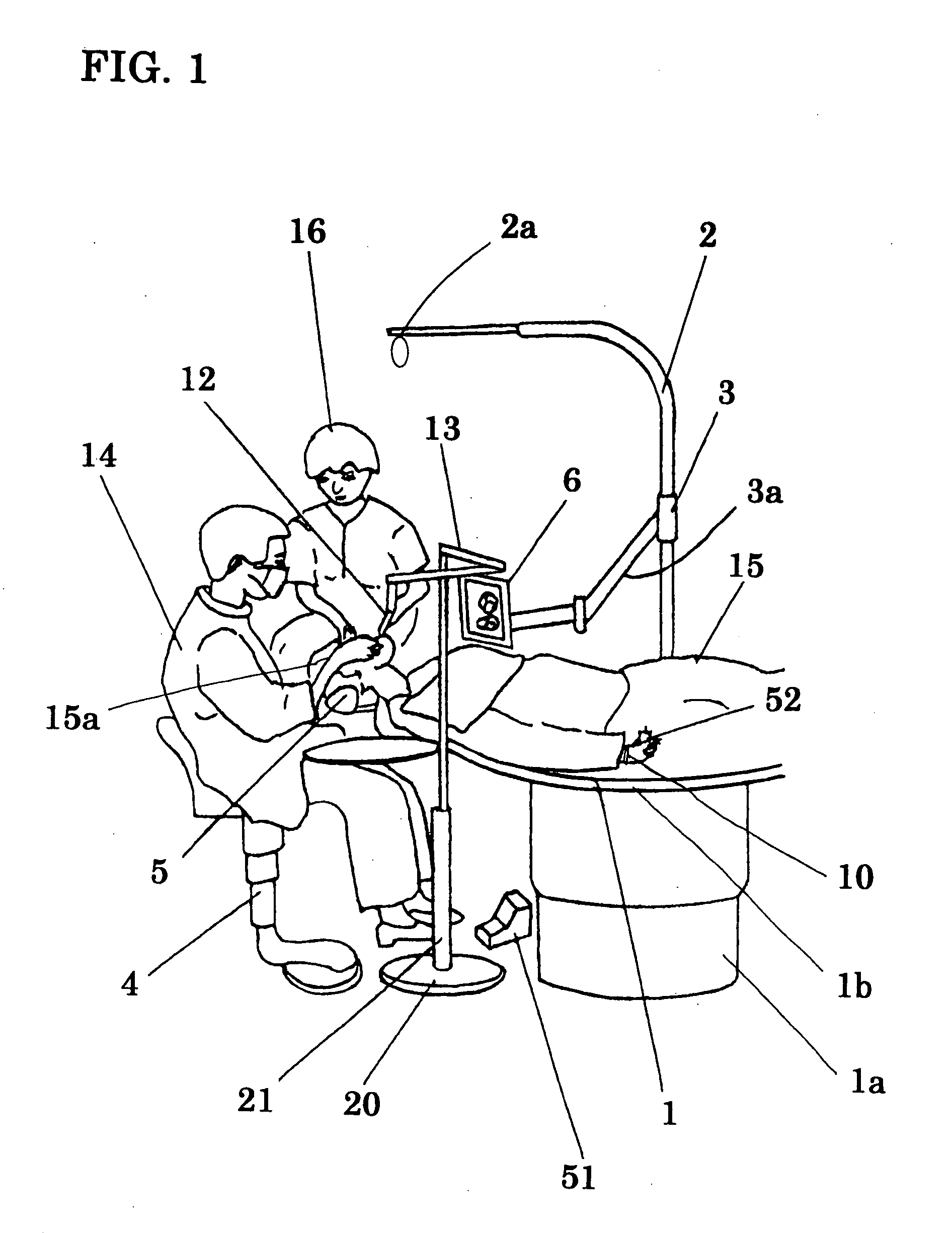
[0071] Referring to FIG. 7, a second embodiment will be described. The same reference numerals as in FIG. 1 to FIG. 6 represent the same names and functions.

[0072] The difference between this embodiment and the first embodiment is in that a patient-specific mirror 17 and a dental-assistant-specific mirror 18 are provided in addition to the first monitor 6. The patient-specific mirror 17 is installed at a position where the patient 15 lying on his / her back on the dental treatment table 1 can see best, and its angle is adjusted so as to reflect the display of the first monitor 6. For example, the patient-specific mirror 17 is rotatably provided on a connecting member 2b, which is provided at the distal end of the lamp post 2 in the vertical direction, and the height or the inclination angle thereof is adjustable. The patient-specific mirror 17 is located substantially right above the eyes of the patient 15, and is disposed at a position where it can be seen easier than the first moni...

third embodiment

[0075] Referring to FIG. 8, a third embodiment of the present invention will be described. The same reference numerals as in FIG. 1 to FIG. 6 represent the same names and functions.

[0076] The difference between this embodiment and the first embodiment is in that a second monitor 7 for a patient and a third monitor 8 for a dental assistant are provided in addition to the first monitor 6.

[0077] The second monitor 7 is installed at a position where the patient 15 lying on his / her back on the dental treatment table 1 can see best. For example, the second monitor 7 is rotatably provided on the connecting member 2b, which is provided at the distal end of the lamp post 2 in the vertical direction, and the height or the inclination angle thereof is adjustable. The second monitor 7 is located at a position where it can be seen easier than the first monitor 6 by the patient 15, and is positioned substantially right above the eyes of the patient 15.

[0078] The third monitor 8 is disposed at ...

fourth embodiment

[0081] Referring now to FIG. 9 and FIG. 10, a fourth embodiment of the present invention will be described. The same reference numerals as in FIG. 1 to FIG. 8 represent the same names and functions.

[0082] The difference between this embodiment and the first, second and third embodiments is in that a camera 112 having two lenses is used as the intraoral camera, and a two-window monitor 109 is employed as the first monitor.

[0083] The intraoral camera 112 is provided with the camera body 36 and the head portion 37. The head portion 37 is rotatably connected to the camera body 36 via a hinge 38, and an upper surface 37a thereof is provided with a first lens 39, a second lens 40, and some lamps 41. The both lenses 39, 40 are disposed in parallel at a predetermined distance, and their angles are adjusted so that they can capture the images of the identical site to be diagnosed and treated from slightly different directions. The lamps 41 are disposed so that the lenses 39, 40 lie in betw...


PUM


Abstract

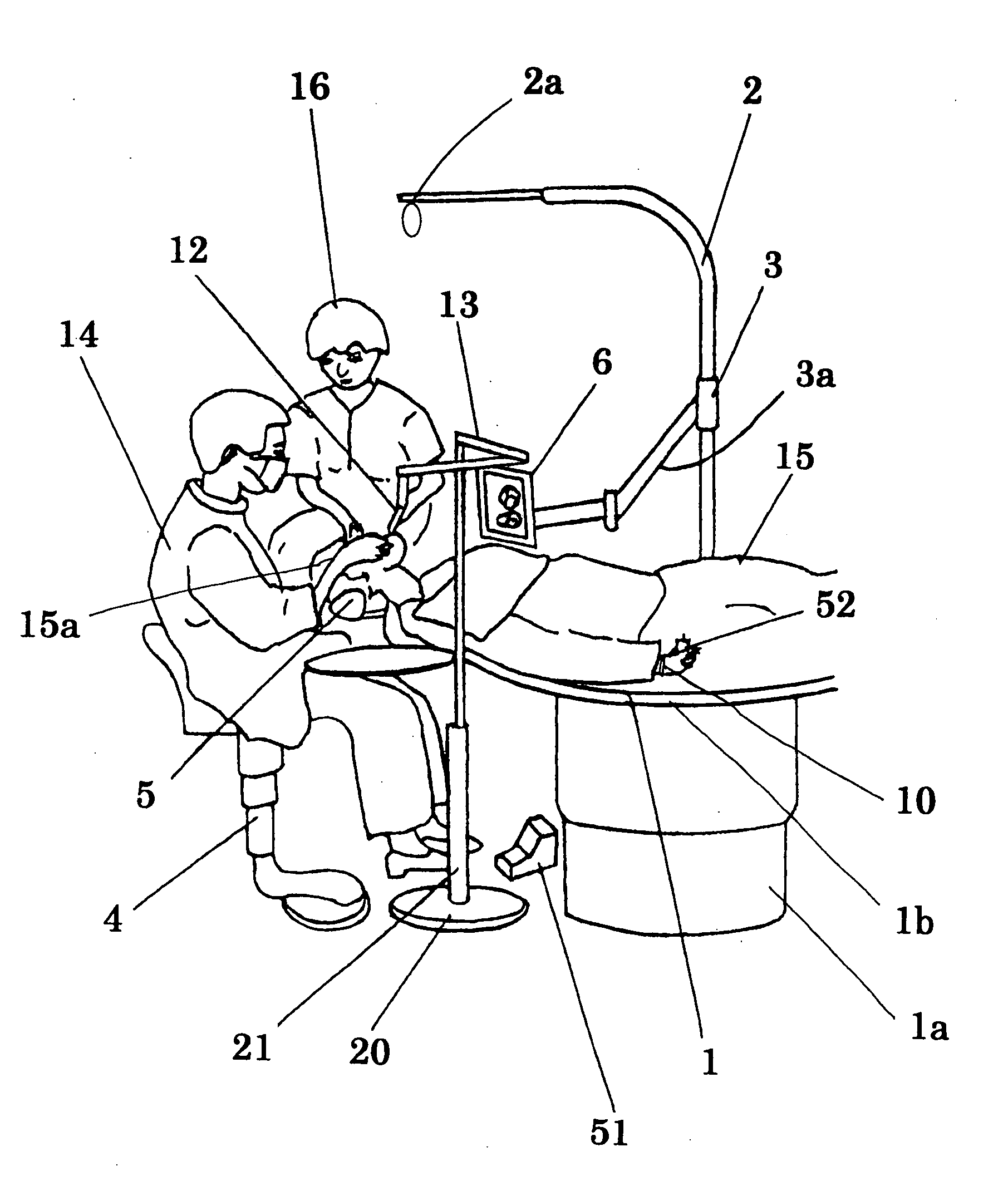
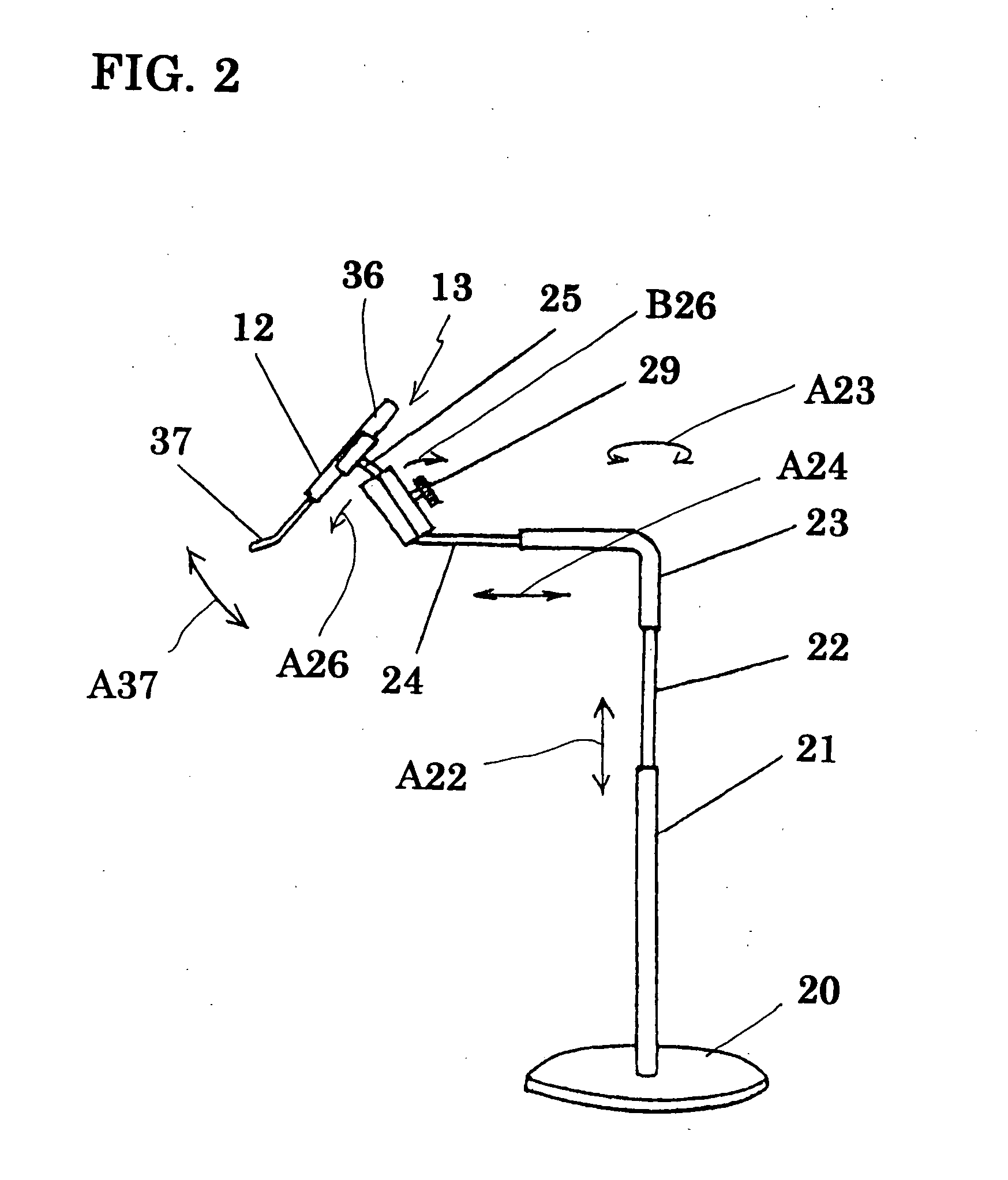
An apparatus for dental diagnosis and treatment includes: a dentist's chair disposed near a dental treatment table; an intraoral camera which can capture moving images in the patient's oral cavity and can be fixed near the patient's mouth; a first monitor installed at a position where the three parties comprising a dentist sitting on the dentist chair, the patient lying on his/her back on the dental treatment table, and a dental assistant assisting the diagnosis and treatment can see, the first monitor displaying the image captured by the intraoral camera, and being able to invert the image in the vertical direction and reverse the image in the lateral direction by the dentist; and a recording device which can record the images captured by the intraoral camera.

Description

BACKGROUND OF THE INVENTION [0001] The present invention relates to an improvement in an apparatus for dental diagnosis and treatment having a dental treatment table provided with an intraoral camera and a monitor for displaying an image obtained by the intraoral camera, and adapted so that a dentist can carry out dental treatment while looking at a moving image in the oral cavity of a patient, which is displayed on the monitor. [0002] An apparatus for dental diagnosis and treatment in prior art is an apparatus for dental diagnosis and treatment in which a dentist gives treatment while directly observing a site to be treated in the oral cavity, and when the dentist carries out treatment using the apparatus for dental diagnosis and treatment, as shown in FIG. 14 the dentist is forced to take an unnatural and uneasy posture with respect to the respective body position of a patient 15A on the dental treatment table 1A, such as bending his / her body or twisting his / her body to the left o...

Claims


Application Information

Patent Timeline
Patent Type & Authority Applications(United States)
IPC IPC(8): A62B1/04A61C19/00A61B1/24A61G15/00A61G15/08A61G15/14
CPCA61B1/00048A61B1/24A61G15/14A61G15/08A61C19/00
Inventor FUJIE, HIDEHIROFUJIE, SUSUMU
Owner FUJIE HIDEHIRO
Why Eureka
Try Eureka