Shipping container

Inactive Publication Date: 2006-01-19
C & E ENTERPRISES INC
View PDF10 Cites 12 Cited by
  • Summary
  • Abstract
  • Description
  • Claims
  • Application Information

AI Technical Summary

Benefits of technology

[0016] Each of the retainers is individually removably mounted onto the mounting rod. Thus, assembly of the retainers onto the mounting rod can be rapidly and easily achieved. Furthermore, in the event that one

Problems solved by technology

The entire assembly operation is labor intensive thus adding to the overall cost of the shipping container 20.
A still further disadvantage of this previously known shipping container is that, in the event that one of

Method used


Image

  • Shipping container
  • Shipping container
  • Shipping container

Examples


Example

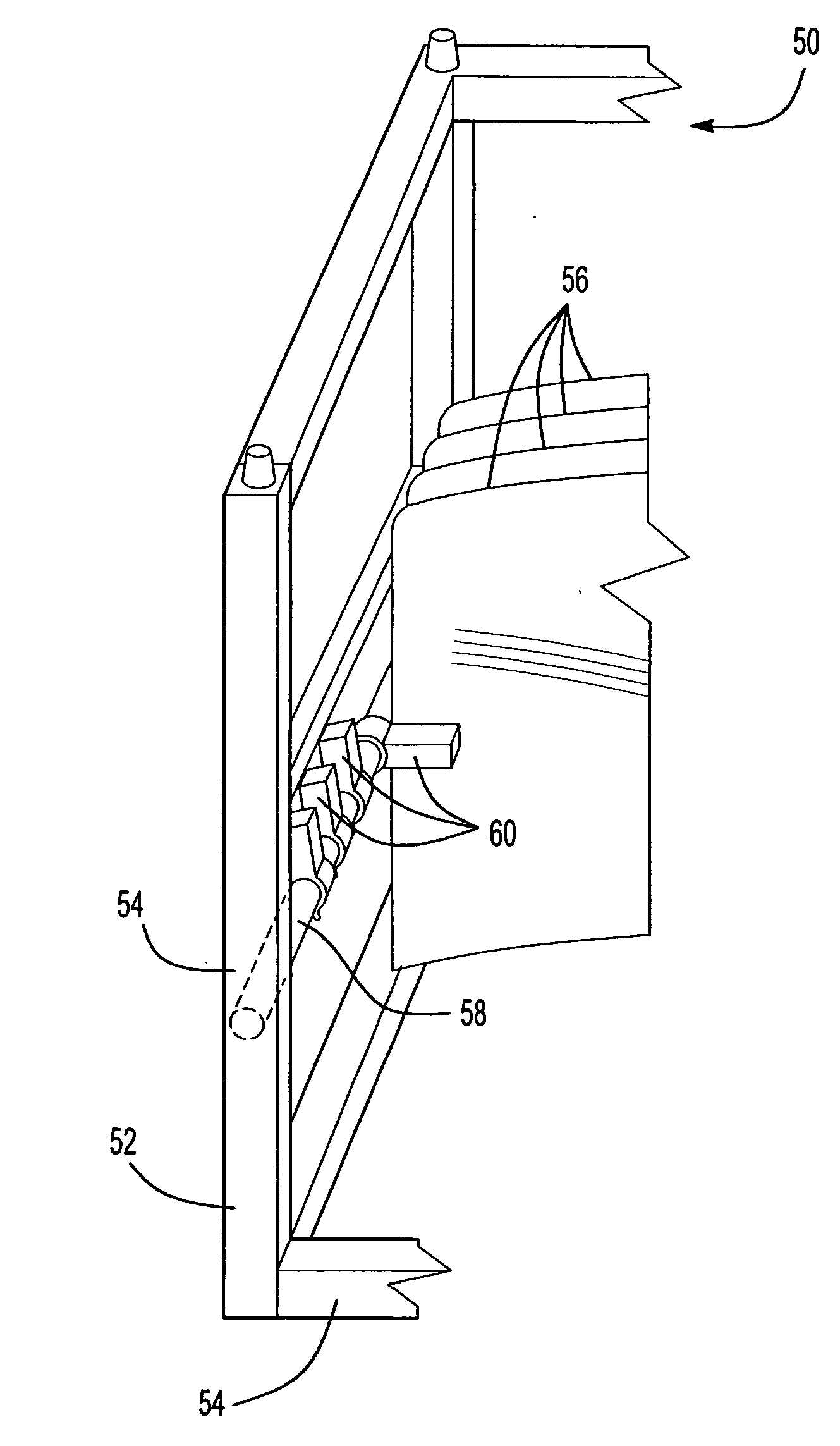
[0024] With reference first to FIG. 5, a preferred embodiment of a shipping carrier 50 of the present invention is shown and comprises a frame 52 which is typically constructed from square metal tubing 54. The carrier 50 illustrated in FIG. 5 is designed to carry a plurality of components 56, such as automotive windshields.

[0025] The carrier 50 includes at least one elongated mounting rod 58 which is secured to the frame 52 so that the rod 58 extends transversely across the frame 52. Although the rod 58 may be solid in cross-sectional shape, the rod 58 more typically is tubular in cross-sectional shape.

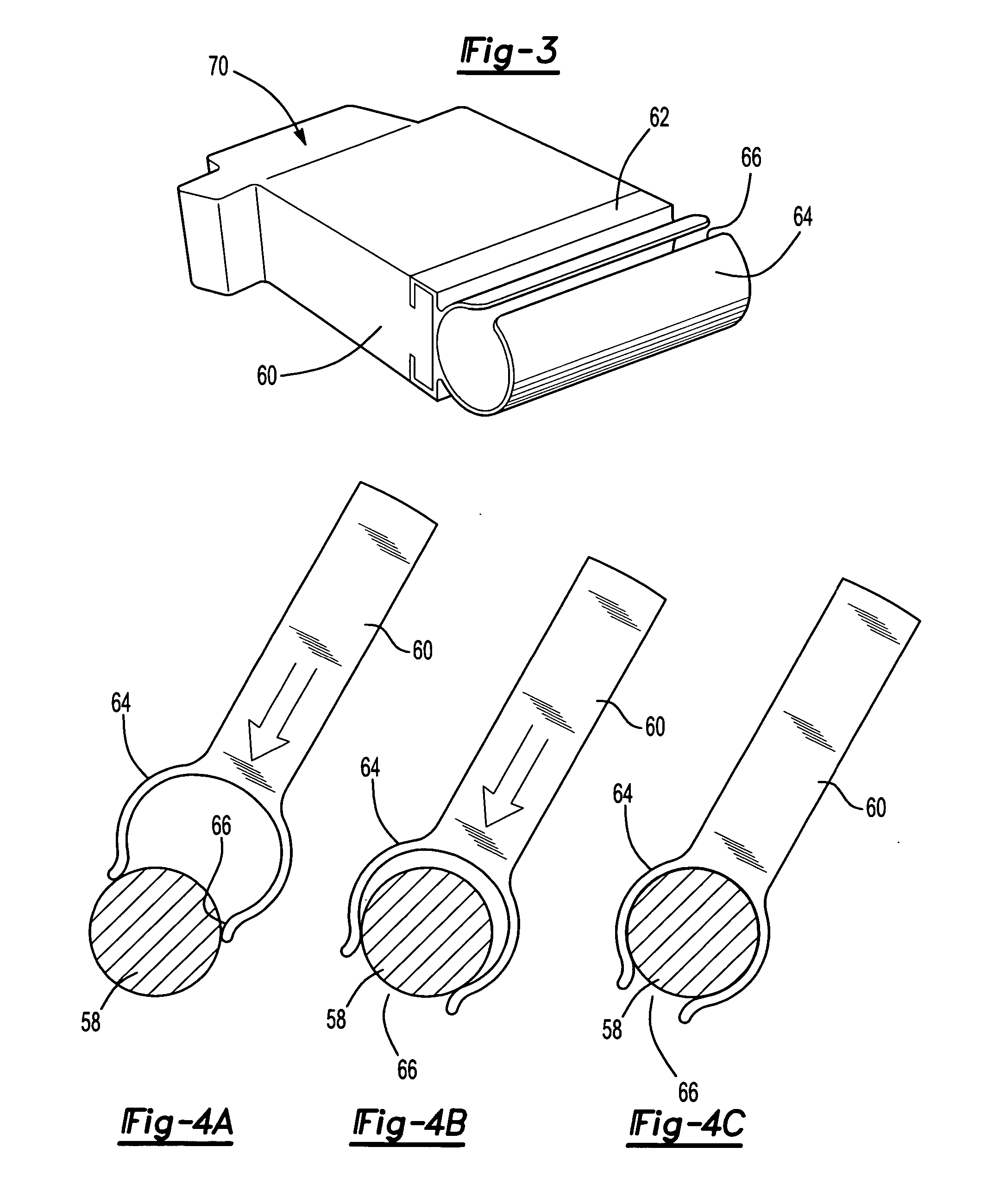
[0026] With reference to FIGS. 5 and 6, a plurality of dunnage fingers 60 are pivotally mounted to the mounting rod 58. As will be subsequently described in greater detail, as the transported components 56 are positioned within the carrier 50, the dunnage fingers 60 are pivoted from a release position illustrated in solid line in FIG. 6, in which the dunnage fingers 60 are disengage...


PUM


Abstract

A shipping carrier having a frame with at least one elongated cylindrical mounting rod extending transversely across the frame. A plurality of retainers each having molded dunnage are provided wherein each retainer has a flexible tubular cylindrical section with an axially extending through slot formed along one side. The cylindrical section has an inside diameter substantially the same as the outside diameter of the mounting rod and the slot has a width less than the outside diameter of the mounting rod. Dunnage is attached to each of the retainers. The retainers are detachably mounted to the mounting rod by inserting the cylindrical section onto the mounting rod through the slot. The retainer is then pivotal on the mounting rod between a holding position and a release position.

Description

CROSS-REFERENCE TO RELATED APPLICATION [0001] The present application is a continuation-in-part of U.S. patent application Ser. No. 10 / 894,228 filed Jul. 19, 2004.BACKGROUND OF THE INVENTION [0002] I. Field of the Invention [0003] The present invention relates generally to shipping containers for components. [0004] II. Description of Related Art [0005] Shipping containers are oftentimes used to ship manufactured components from the place of manufacture and to their place of assembly. For example, in the automotive industry, many of the individual components of the automotive vehicles, such as the automotive windshields, are manufactured at one location and then shipped to a different location for assembly on the automotive vehicle. [0006] With reference now to FIGS. 1 and 2, a typical prior art shipping container 20 of the type used in the automotive industry is shown. The shipping container 20 includes a rigid frame 22 which is typically constructed of rectangular metal tubing 24. ...

Claims


Application Information

Patent Timeline
IPC IPC(8): B31B1/00
CPCB65D19/44B65D85/48B65D2585/6882B65D2519/00975B65D2519/0082
Inventor FARLEY, CHARLESHEFNER, CRAIG
Owner C & E ENTERPRISES INC
Why Eureka
Try Eureka