

Disk housing case
a technology for storing devices and cases, applied in the field of storage devices, can solve the problems of troublesome insertion and removal procedures, limited amount of information capable of being recorded by writing and editing content on the roughened index portion, and inconvenient to use,
- Summary
- Abstract
- Description
- Claims
- Application Information
AI Technical Summary
Benefits of technology
Problems solved by technology
Method used
Image

Examples
embodiment 1
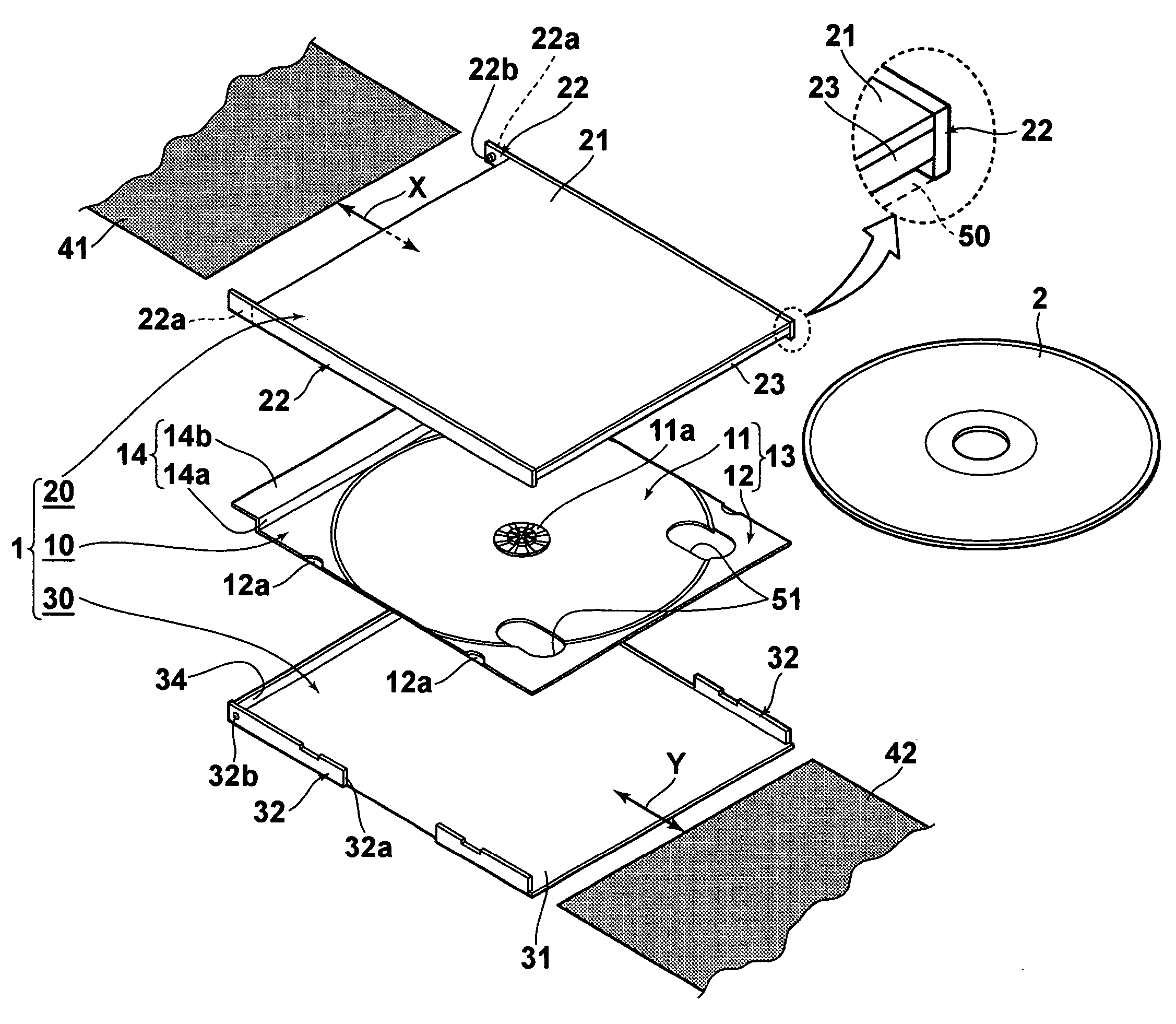
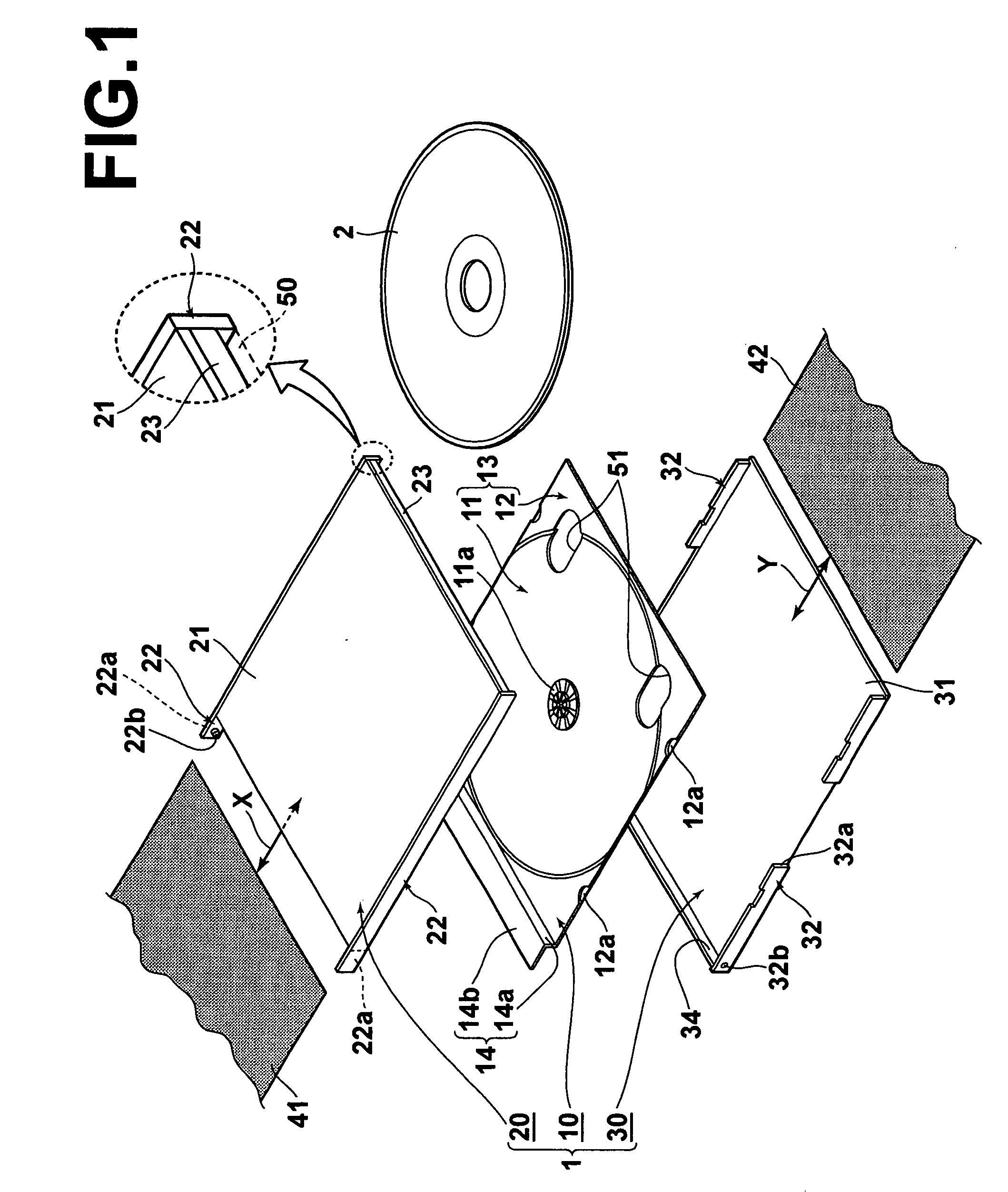
[0073] A disk housing case according to a first embodiment of the present invention will be described with reference to FIGS. 1 through 6B. The disk housing case of the first embodiment is a case for housing a recording media disk, such as CD's (Compact Discs), DVD's (Digital Versatile Discs), and BD's (Blu-ray Discs). The first embodiment is characterized by the entry / exit structure of indexes.
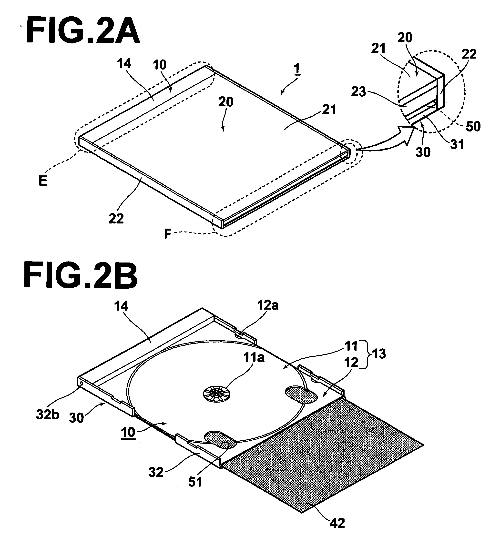
[0074]FIG. 1 is an exploded perspective view of a disk housing case 1 in a closed state. FIGS. 2A and 2B are perspective views of the disk housing case 1 in a closed state (a front case half is omitted in FIG. 2B). FIG. 3 is a plan view of the disk housing case 1 in an open state. FIG. 4 is a bottom view of the disk housing case 1 in an open state. FIG. 5A is a front view of the disk housing case 1 (a rear view is the same as the front view, and therefore is omitted). FIG. 5B is a sectional view taken along line V-V of FIG. 3. FIG. 5C is a magnified partial view of an end F of FIG. 5B. FIG. ...
first embodiment
Modifications to the First Embodiment
[0102] In the first embodiment, the slit 50, which is the index entry / exit opening, is formed by not providing a side wall at the end F of the rear case half 30, and by providing the side wall 23, which is shorter than the side walls 22, at the end F of the front case half 20. However, the present invention is not limited to such a configuration. For example, the side wall 23 may not be provided at the end F of the front case half 20 and a side wall 33 may be provided at the end F of the rear case half 30 having the slit 50 formed therein, as illustrated in FIG. 7.
[0103] In the first embodiment, two contact openings 51 are provided in the disk tray 10 toward the side of the index entry / exit opening such that they straddle the disk housing recess 11 and the flared portion 12. By this configuration, both thumbs can contact the rear side index 42 through the contact openings 51. In addition, because the areas of the contact openings are comparative...
second embodiment
Modifications to the Second Embodiment
[0123] In the second embodiment, the slit 50, which is the index entry / exit opening, is formed by not providing a side wall at the end F of the rear case half 30, and by providing the side wall 23, which is shorter than the side walls 22, at the end F of the front case half 20, similar to the configuration of the first embodiment. However, the present invention is not limited to such a configuration. For example, the side wall 23 may not be provided at the end F of the front case half 20 and a side wall 33 may be provided at the end F of the rear case half 30 having the slit 50 formed therein, as illustrated in FIG. 7.
[0124] As the second embodiment, a configuration has been described, in which a single contact opening 52 is formed as a substantially semicircular cutout at the end of the rear case half 30 toward the index entry / exit opening. The location, shape, and number of the contact opening 52 are not limited to those of the second embodim...
PUM
| Property | Measurement | Unit |
|---|---|---|
| colors | aaaaa | aaaaa |
| transparent | aaaaa | aaaaa |
| areas | aaaaa | aaaaa |
Abstract
Description
Claims
Application Information