Internally illuminated sign

a technology of illuminated signs and signs, applied in the field of illuminated signs, can solve the problems of difficult reading of letters, impaired appearance, and reduced retroreflectivity as a whole, and achieve the effects of facilitating light entry, effective intensification of light transmission, and difficult effective light transmission

Inactive Publication Date: 2006-02-02
NIPPON CARBIDE KOGYO KK
View PDF13 Cites 32 Cited by
  • Summary
  • Abstract
  • Description
  • Claims
  • Application Information

AI Technical Summary

Benefits of technology

[0075] Adoption of above-described light-guiding plate or planar luminophor is preferred because it facilitates entrance of the light emitted by the illuminator used in the retroreflective internally illuminated sign of the present invention into the prismatic retroreflective elements from the back, at an entrance angle of 0 to 30° to the normal line of the surface(s) constituting the information display section, to effectively intensify the light transmitting from the back to the front of the sign. Where the entrance angle of the light exceeds 30°, effective transmission of the light becomes difficult and such is undesirable.
[0076] Above-described information display section and illuminator are integrated by a housing which encloses them. The shape of the housing is not critical, which can be suitably selected among rectangular parallelepipeds, column

Problems solved by technology

The sheeting, therefore, is subject to a problem that its retroreflectivity as a whole is markedly reduced.
The products furthermore are subject to problems that their appearances are impaired or relatively small-sized letters displayed thereon are difficult of reading, because a uniform appearance cannot be achieved with above encapsulation structures wherein the retroreflective areas and sealing bond areas differ in color and qualitative impression.
Also in such retroreflective sheeting as proposed by Benson, which uses prismatic retroreflective elements having separation surfaces therebetween, the prismatic retroreflective elements are absent at the areas where the separation surfaces are provided, similarly to the elements disclosed in Bradshaw, and hence the sheeting is subject to a probl

Method used


Image

  • Internally illuminated sign
  • Internally illuminated sign
  • Internally illuminated sign

Examples


Embodiment Construction

[0090] Hereinafter the invention is explained in further details, referring to the drawings.

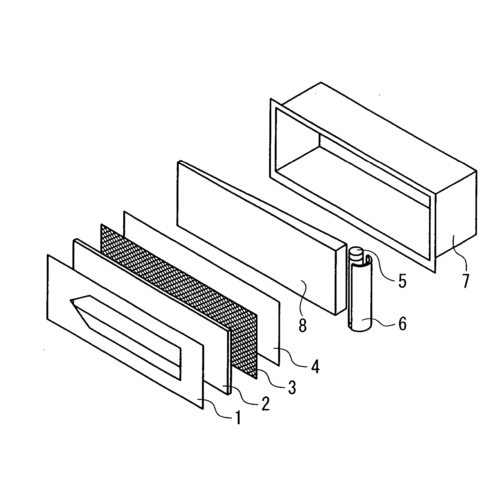
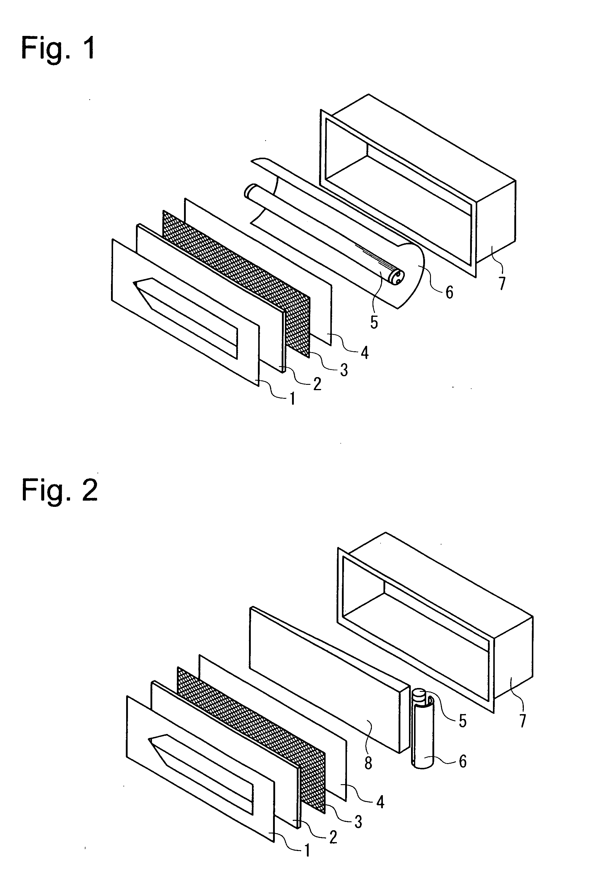
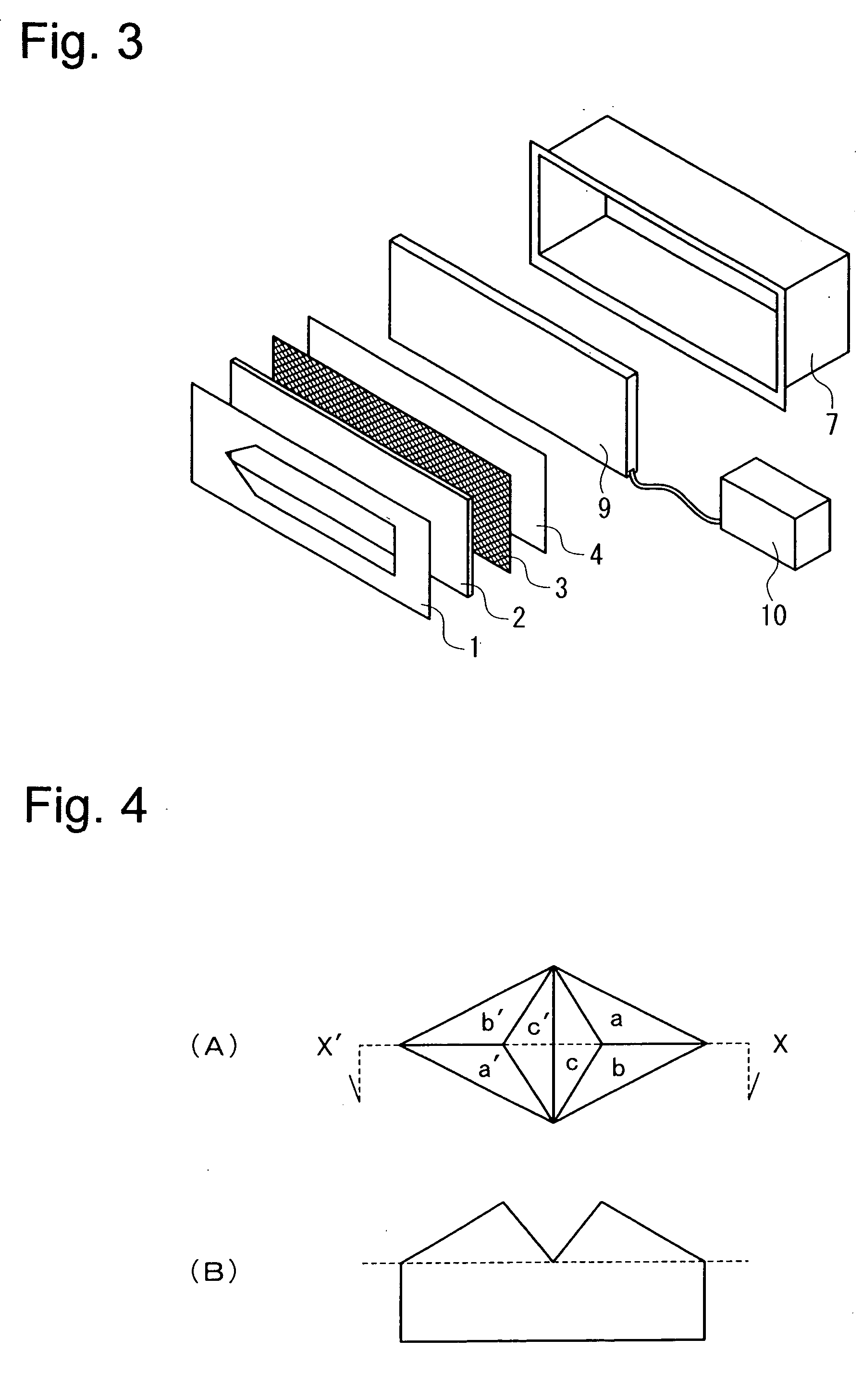
[0091]FIG. 1 is a schematic view showing an example of working embodiment of an internally illuminated sign according to the present invention. The information display section having a surface which is retroreflective to the light from the front surface of the sign and is transmissive to the light from the interior of the sign, is composed of an information display layer (1), surface-protective layer (2), retroreflective layer (3) and a light-scattering layer (4). An illuminator disposed on the back of the information display section is composed of a light source (5) and a back reflection layer (6). Furthermore, these information display device (1-4) and illuminator (5, 6) are enclosed and held in a housing (7).

[0092] In the working embodiment illustrated in FIG. 1, the information display layer (1) is installed in front of the surface-protective layer (2) as an independent layer, but it ca...


PUM


Abstract

The invention provides an internally illuminated sign comprising an information display section having at least one flat or curved surface which retroreflects light coming from the front of said sign and transmits light from the interior of said sign; an illuminator disposed behind the information display section; and a housing which encloses and holds said information display section and the illuminator. Those retroreflective elements used in said information display section are prismatic retroreflective elements according to the principle of total internal reflection, a large number of which are densely arranged to form a continuous retroreflective plane, at least the retroreflecting area of the back of said large number of prismatic retroreflective elements has no bonded area to other layer(s).

Description

TECHNICAL FIELD [0001] This invention relates to an internally illuminated sign of novel construction, which comprises an information display section having a surface which retroreflects light coming from the front of the sign and transmits light coming from the interior of the sign, an illuminator disposed on the back of said display section; and a housing enclosing and holding these information display section and illuminator. [0002] More particularly, the invention relates to a retroreflective, internally illuminated sign which comprises [0003] an information display section having at least one flat or curved surface which retroreflects light coming from the front of the sign and transmits light from the interior of the sign; an illuminator disposed on the back of the information display section; and a housing enclosing and holding these information display section and illuminator, and which is characterized in that [0004] the retroreflective element used in said information dis...

Claims


Application Information

Patent Timeline
IPC IPC(8): G09F13/18F21V8/00G09F13/04G09F13/14G09F13/16
CPCG02B6/0053G09F13/16G09F13/14G09F13/04
Inventor MATSUDA, AKIHIROHAMADA, YUTAKAMIMURA, IKUO
Owner NIPPON CARBIDE KOGYO KK
Why Eureka
Try Eureka