Excavating wear member

a technology of wear members and wear plates, applied in soil shifting machines/dredgers, constructions, etc., can solve the problems of high cost, complex construction and use, and safety hazards of installing and removing personnel

Inactive Publication Date: 2006-02-23
HENSLEY INDUSTRIES INC
View PDF11 Cites 38 Cited by
  • Summary
  • Abstract
  • Description
  • Claims
  • Application Information

AI Technical Summary

Benefits of technology

[0015] In a third representative embodiment of the tooth point / adapter assembly, the tooth point interior side surface recess is eliminated and replaced with a locking lug disposed on and projecting inwardly from an interior side surface of the point rearwardly of a connector opening therein, and the outwardly extending longitudinal connector pin portion has a slot therein. With the connector pin in its release / installation rotational position, the tooth point is rearwardly moved onto the adapter nose to thereby cause the point lug to pass rearwardly through and beyond the connector pin slot. The connector pin is then rotated to its locking rotational position to thereby cause its outwardly extending longitudinal portion to forwardly block the point lug and prevent the point from being forwardly removed from the adapter nose. When it is desired to remove the point from the adapter nose, the connector pin is simply rotated back to its release rotational position, and the point is forwardly removed from the adapter nose, with the point lug passing forwardly through the connector pin slot during such removal.

Problems solved by technology

This conventional need to pound in and later pound out the connector structure can easily give rise to a safety hazard for the installing and removing personnel.
While these alternative connector structures desirably eliminate the need to pound a connector structure into and out of an adapter nose they typically present various other types of problems, limitations and disadvantages including, but not limited to, complexity of construction and use, undesirably high cost, and the necessity of removing the connector structure prior to removal or installation of the replaceable wear member.

Method used


Image

  • Excavating wear member
  • Excavating wear member
  • Excavating wear member

Examples


Embodiment Construction

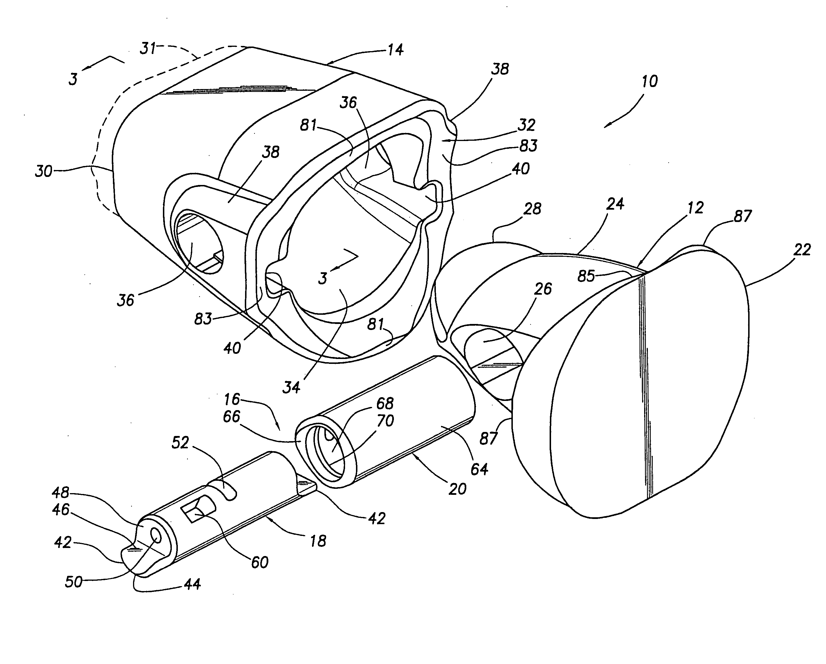
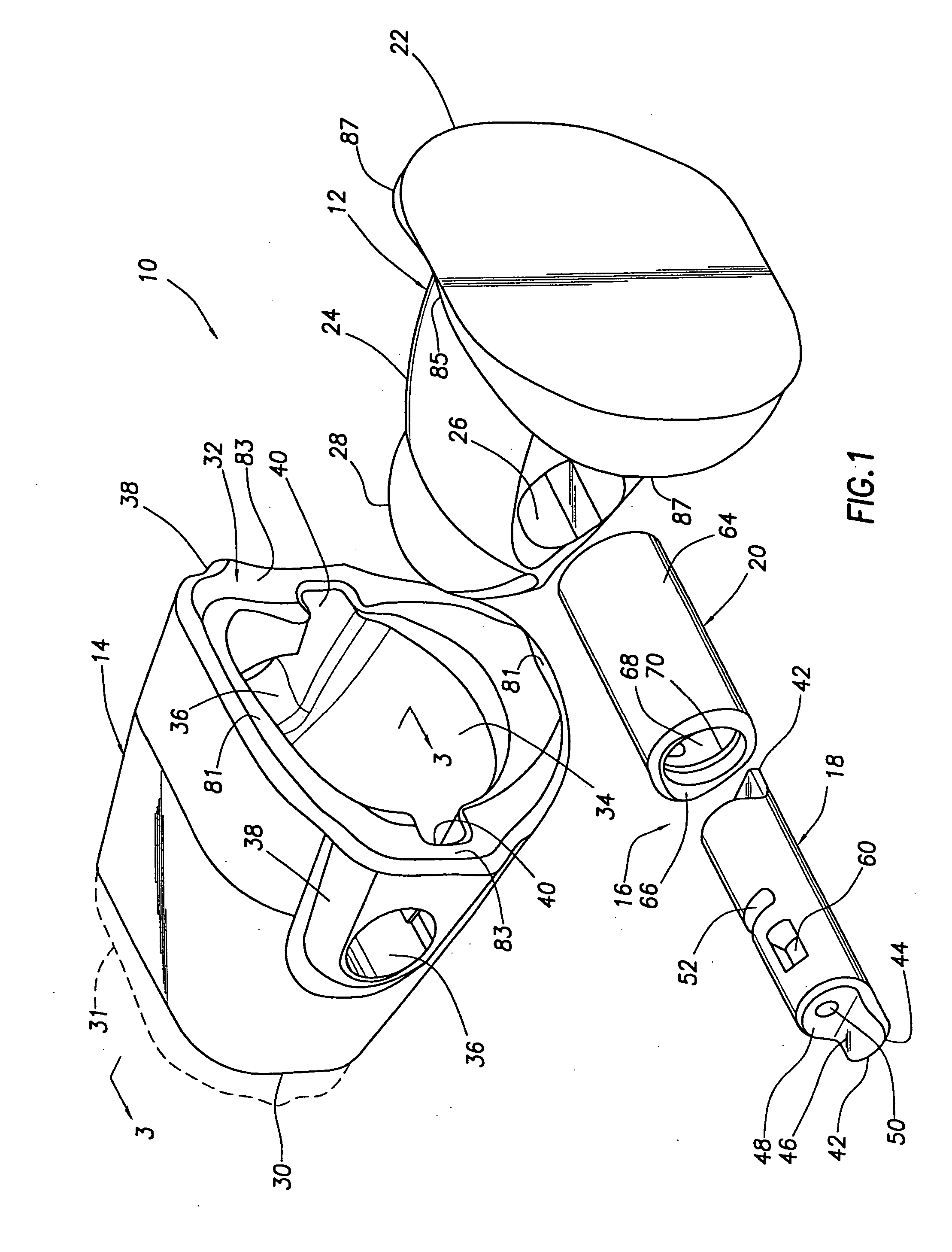
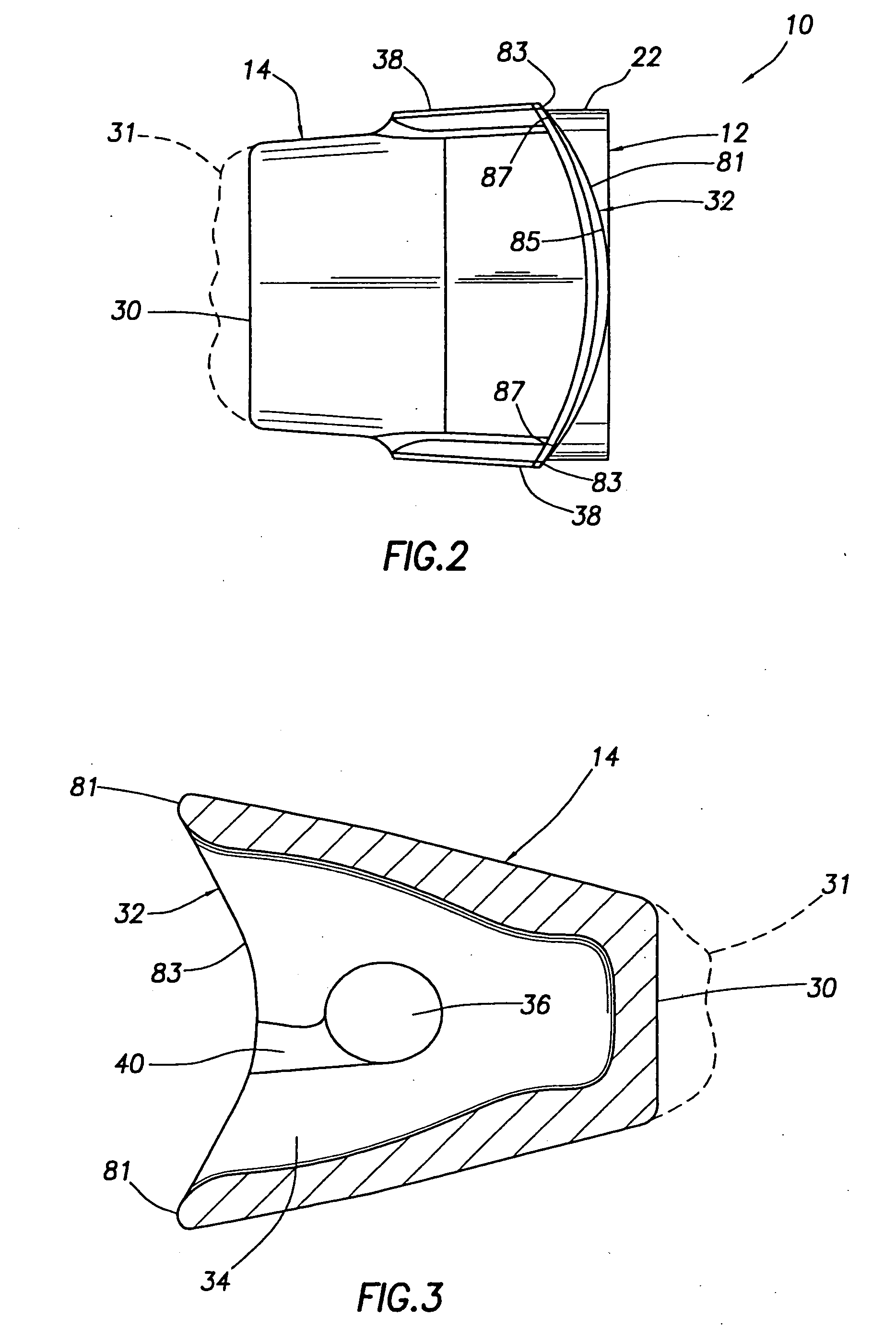
[0045] Referring initially to FIGS. 1-7, in a first embodiment thereof this invention provides an excavating tooth assembly 10 including a support structure representatively in the form of an adapter 12, a wear member representatively in the form of a replaceable tooth point 14, and a rotatable connector pin assembly 16 having a pin portion 18 and a hollow body or cartridge portion 20.

[0046] Adapter 12 has a rear base portion 22 from which a nose portion 24 forwardly projects, the nose portion 24 having a horizontally elongated elliptical cross-section along its length, and a non-circular transverse connector opening 26 extending horizontally therethrough between the opposite vertical sides of the nose 24.

[0047] The replaceable point 14 has a front end 30 on which a suitable leading edge 31 (a portion of which is shown in phantom) is disposed, a rear end 32 through which a nose-receiving socket 34 forwardly extends, and a horizontally opposed pair of horizontally elongated ellipti...


PUM


Abstract

A rotatable connector pin assembly is disposed within an opening in an adapter nose, with opposite ends of the pin portion of the assembly extending outwardly beyond opposite sides of the adapter nose in axially fixed orientations relative thereto, and is used to captively and releasably retain a replaceable excavating tooth point on the nose. The configuration of the opposite pin ends permits the overall pin assembly to remain in the adapter nose during removal of the point and replacement thereof, with the pin being rotatable between a first orientation in which its ends permit removal of a point from the nose, or installation of a point on the nose, and a second orientation in which the opposite pin ends block removal of the point from the adapter nose.

Description

CROSS-REFERENCE TO RELATED APPLICATION [0001] This application is a division of copending U.S. application Ser. No. 10 / 005,935 filed on Dec. 3, 2001 and entitled “EXCAVATING TOOTH ASSEMBLY WITH ROTATABLE CONNECTOR PIN STRUCTURE”.BACKGROUND OF THE INVENTION [0002] The present invention generally relates to material displacement apparatus and, in a preferred embodiment thereof, more particularly relates to apparatus for releasably coupling a replaceable excavating tooth point or other wear member to an associated adapter nose structure. [0003] A variety of types of material displacement apparatus are provided with replaceable wear portions that are removably carried by larger base structures and come into abrasive, wearing contact with the material being displaced. For example, excavating tooth assemblies provided on digging equipment such as excavating buckets or the like typically comprise a relatively massive adapter portion which is suitably anchored to the forward bucket lip and ...

Claims


Application Information

Patent Timeline
Patent Type & Authority Applications(United States)
IPC IPC(8): E02F9/28
CPCE02F9/2833E02F9/2825
Inventor ROBINSON, HOWARD W.SHAMBLIN, WAYNE A.HART, BRUCE L.
Owner HENSLEY INDUSTRIES INC
Why Eureka
Try Eureka