Engine diagnostic apparatus and method that analyzes the output of a driven electric power generator

a technology of diagnostic equipment and engine, applied in the direction of machines/engines, electric control, instruments, etc., can solve the problems of not having a method or device that assesses the operation performance of engines to diagnose problems or achieve optimal performan

Inactive Publication Date: 2006-03-02
KAYSER WILLIAM M
View PDF2 Cites 28 Cited by
  • Summary
  • Abstract
  • Description
  • Claims
  • Application Information

AI Technical Summary

Problems solved by technology

In the current state of the art, no methods or devices assess the operational performance of engines to diagnose problems or achieve optimu

Method used


Image

  • Engine diagnostic apparatus and method that analyzes the output of a driven electric power generator
  • Engine diagnostic apparatus and method that analyzes the output of a driven electric power generator
  • Engine diagnostic apparatus and method that analyzes the output of a driven electric power generator

Examples


Embodiment Construction

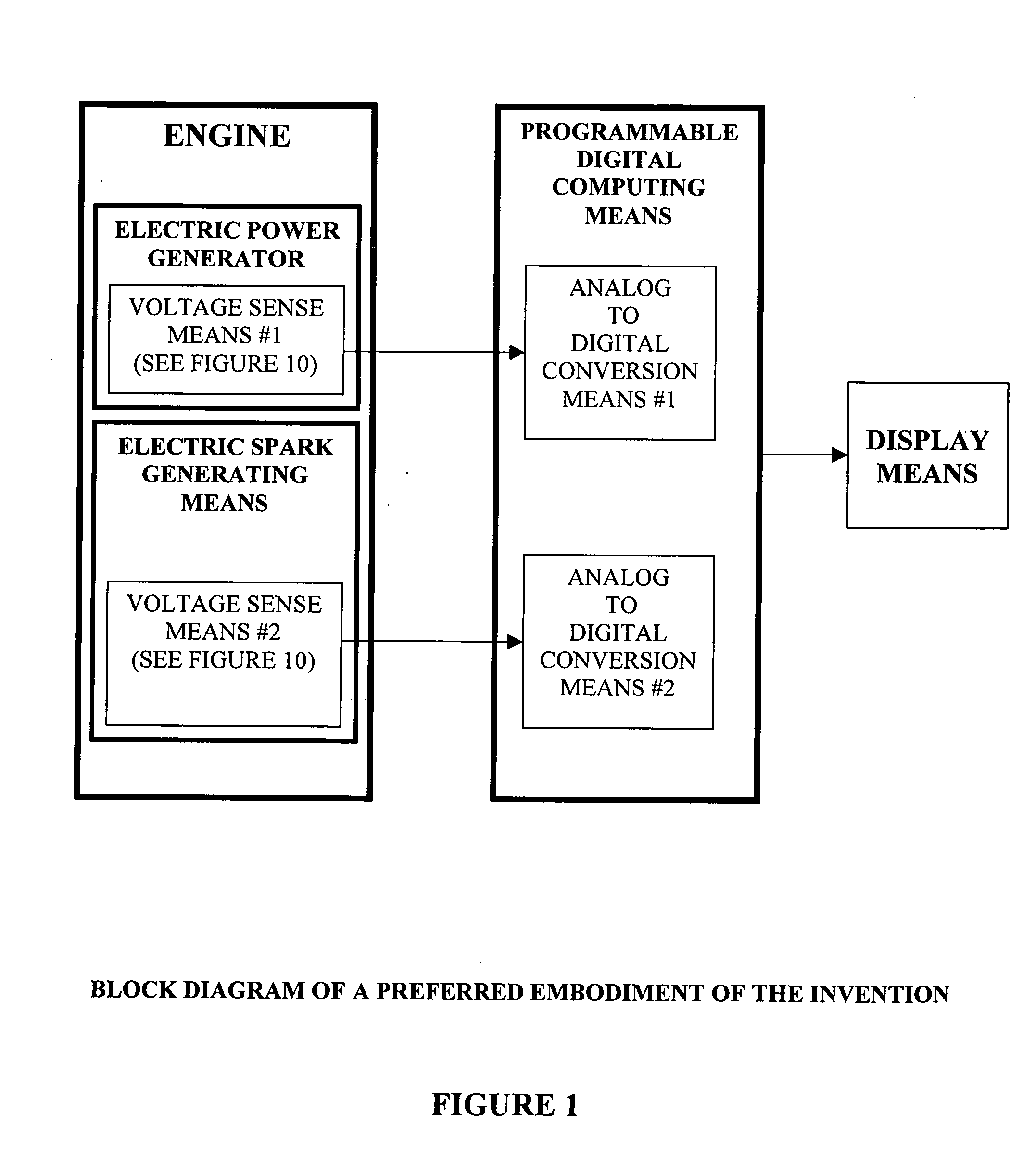
[0018] A preferred embodiment of the invention uses standard electrical components, a digital computer and software to detect and process signals from battery voltages. A block diagram of these devices is shown in FIG. 1. A schematic of these devices is shown in FIG. 10. The circuitry of a preferred embodiment is shown inside the box labeled 10, Voltage Sensor #1. It has diode 5, capacitor 6 and resistors 7 and 8. Diode 5, resistor 6 and resistor 7 are connected in series, while capacitor 8 is connected in parallel with resistor 6. Diode 5 is a standard signal diode, resistor 6 is a 10,000,000 ohm resistor, resistor 7 is a 200,000 ohm resistor, and capacitor 8 is a 5 micro-farad capacitor. Voltage sensor #1 connects first to Electric Power Generating Means 40 at node 1, and it connects second to ENGINE BLOCK 20 at node 2. Conductor 4 connects the output of Voltage Sensor #1 to Analog to Digital Converter #1 shown in FIG. 1. Voltage sensor #2 clamps around the spark plug wire with co...


PUM


Abstract

In the present art, the closest detectable points in time that are available for electronic engine analyzers to ascertain of the functionality of most engines are the times when spark pulses occur. The present invention utilizes the output of driven electric power generators to both ascertain when those sparks (or similar signals in engines without sparks) occur, and to ascertain how engines are functioning between those sparks. The invention takes advantage of the fact that during the time between cylinder firings, the output voltage of engine-driven electric power generators is directly related to the instantaneous functionality of the engine. By displaying and analyzing the output of driven electric power generators, the invention's apparatuses and methods are able to show previously unavailable useful information related to the functionality of engines, including the compression inside each cylinder and the power produced by each cylinder.

Description

FIELD OF THE INVENTION [0001] The invention is in the field of diagnostic analyzers that show combustion-based engine functionality by processing output signals from engine-driven devices. BACKGROUND OF THE INVENTION [0002] In the current state of the art, no methods or devices assess the operational performance of engines to diagnose problems or achieve optimum performance based on a display or an analysis of the output signals of electric generators that are coupled to and driven by said engines. [0003] U.S. Pat. No. 4,812,979 titled “Method and Apparatus for Analyzing the Performance of an Internal Combustion Engine” issued to Hermann and U.S. Pat. No. 5,258,753 titled “Digital Engine Analyzer” issued to Jonker both teach engine analyzers in which spark pulse intervals are used to show how well an engine is performing. U.S. Pat. No. 3,972,230 titled “Detecting Malfunction in Cylinders of Internal Combustion Engines” issued to Hanson connects a tachometer to an engine and uses its...

Claims


Application Information

Patent Timeline
IPC IPC(8): G06F19/00F02P17/00
CPCF02D29/06G01M15/044F02D41/1497
Inventor KAYSER, WILLIAM M.
Owner KAYSER WILLIAM M
Why Eureka
Try Eureka