Capacitor unit
- Summary
- Abstract
- Description
- Claims
- Application Information
AI Technical Summary
Problems solved by technology
Method used
Image

Examples
first exemplary embodiment
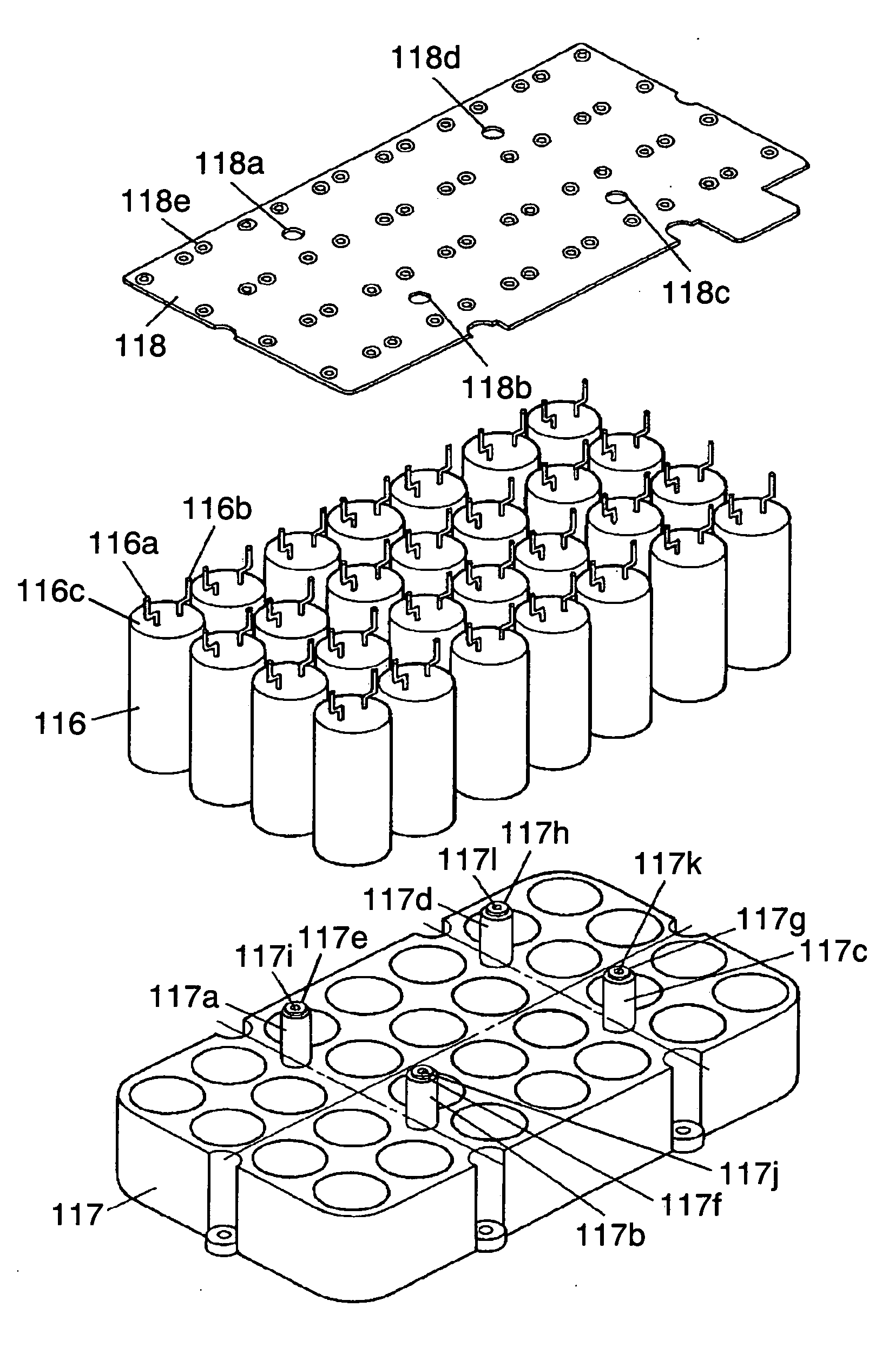
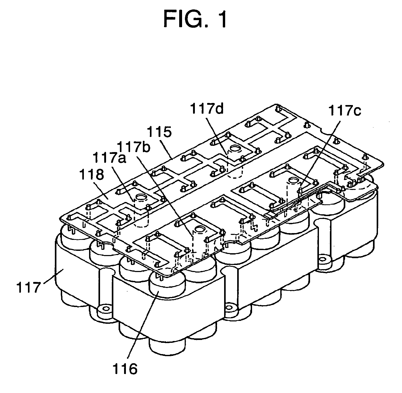
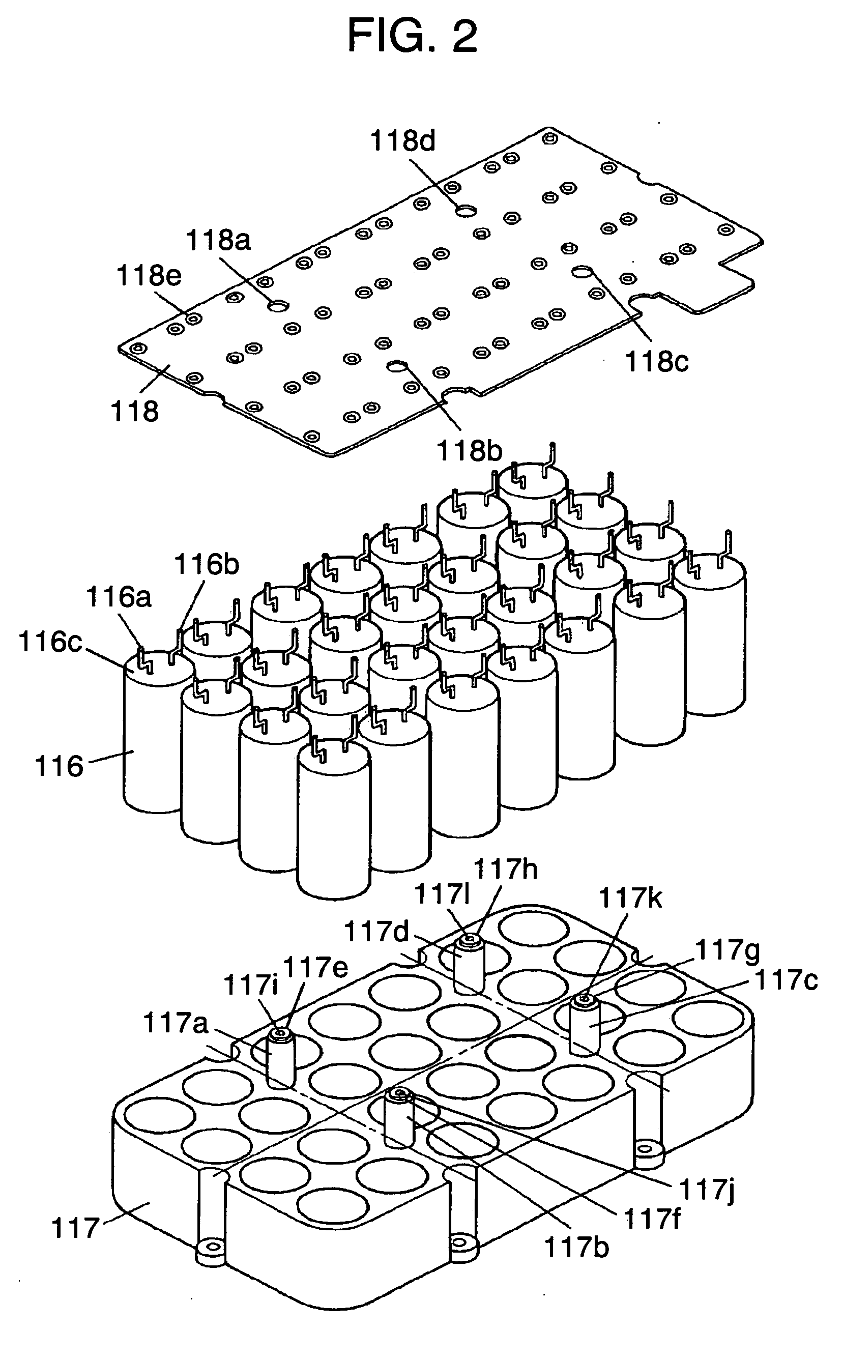
[0118] The above-mentioned conventional capacitor unit is used in a state in which the capacitor unit is attached to a case, equipment to be used, or the like, via attaching holes 501b provided on circuit board 501. However, depending upon the attaching state, since entire weight (several hundreds grams to several kilograms) of plurality of capacitors 502 is applied to one circuit board 501, circuit board 501 may be distorted and deformed. Depending upon using conditions, in particular, when vibration is applied, there may be problems that attaching hole 501b on circuit board 501 or circuit board 501 main body may be broken, or crack may occur in a soldering portion for electrically connecting a pair of lead wires 502b and 502c of capacitor 502 to a wiring circuit provided on circuit board 501.
[0119] The present invention is made to solve such problems with a prior art capacitor unit. Thus, it is an object of the present invention to provide a capacitor unit having high reliability...
second exemplary embodiment
[0148] In the above-mentioned conventional capacitor unit, depending upon the attaching state, there may be problems that entire weight (several hundreds grams to several kilograms) of plurality of capacitors 502 is applied to one circuit board 501, so that circuit board 501 may be distorted and deformed; and depending upon using conditions, in particular, when vibration is applied, attaching hole 501b of wiring board 501 and circuit board 501 main body may be broken. Alternatively, there is a problem that crack may occur in the soldering portion for electrically connecting pair of lead wires 502b and 502c of capacitor 502 to a circuit formed on circuit board 501. Furthermore, when abnormal current flows in capacitor 502, explosion-proof valve 502d provided on metal case 502a of capacitor 502 operates, driving electrolyte, with which capacitor device housed inside of metal case 502a is impregnated, is released from explosion-proof valve 502d. However, this released driving electroly...
third exemplary embodiment
[0170] A conventional method has a shortcoming that the withstand voltage of a capacitor is low due to its nature. Therefore, in order to obtain a necessary voltage, it is necessary to use a plurality of capacitors connected in series. Furthermore, depending upon a necessary energy amount, the series-connected capacitors need to be used in parallel connection. In addition, it is necessary to provide a control circuit for charging and discharging the capacitors.
[0171] Although properties of capacitors are being focused, few proposals have been made on a structure capable of enduring the lifetime of a vehicle, etc. as a unit of emergency power supply obtained by integrating a plurality of capacitors and control circuit with each other.
[0172] The present invention also solves the above-mentioned problem, and configures a unit of a capacitor block including a plurality of capacitors and a control circuit portion for controlling its charge and discharge, thereby improving the reliabili...
PUM
 Abstract
Description
Claims
Application Information
 - R&D Engineer
- R&D Manager
- IP Professional
- Industry Leading Data Capabilities
- Powerful AI technology
- Patent DNA Extraction
Browse by: Latest US Patents, China's latest patents, Technical Efficacy Thesaurus, Application Domain, Technology Topic.
© 2024 PatSnap. All rights reserved.Legal|Privacy policy|Modern Slavery Act Transparency Statement|Sitemap