
Modular platform, walkway or ramp

a module, platform technology, applied in the direction of ramps, balustrades, building scaffolds, etc., can solve the problems of difficult to transport the components required to form a ramp, the ramp of this us specification has a number of significant limitations, and cannot be usually duplicated for other buildings

Inactive Publication Date: 2006-03-23
SUGGATE TREVOR ROSS
View PDF16 Cites 28 Cited by
  • Summary
  • Abstract
  • Description
  • Claims
  • Application Information

AI Technical Summary

Benefits of technology

[0039] Suitably the modular apparatus and assembly of the respective fifth and sixth aspect of the present invention further include one or more prefabricated handrails, each of the prefabricated handrails comprising one or more rails supported by one or more handrail uprights, the prefabricated handrails being arranged for attachment to one or more said deck supports. Suitably, the prefabricated handrails are arranged for attachment to the prefabricated moveable member. The prefabricated handrails preferably include two handrail uprights which are preferably balusters. The prefabricated handrails ...

Problems solved by technology

While ramps can be retrofitted to buildings, they are typically designed for a specific building and therefore cannot usually be duplicated for other buildings.
However, the ramp of this US specification has a number of significant limitations.
Firstly, the support stand is relatively bulky making it difficult to transport the components which are required to form a ramp.
Secondly, the range of height adjustment is quite limited and thirdly, height adjustment of each stand is reasonably time consuming as it involves alignment of holes formed in each end of two support rails with holes of support posts for subsequent insertion of two locating bolts.
However, the ramps disclosed in these Australian patents appear to be quite cumbersome and costly to manufacture.
Furthermore, their stability may be less than desirable in certain applications.

Method used


Image

  • Modular platform, walkway or ramp
  • Modular platform, walkway or ramp
  • Modular platform, walkway or ramp

Examples


Embodiment Construction

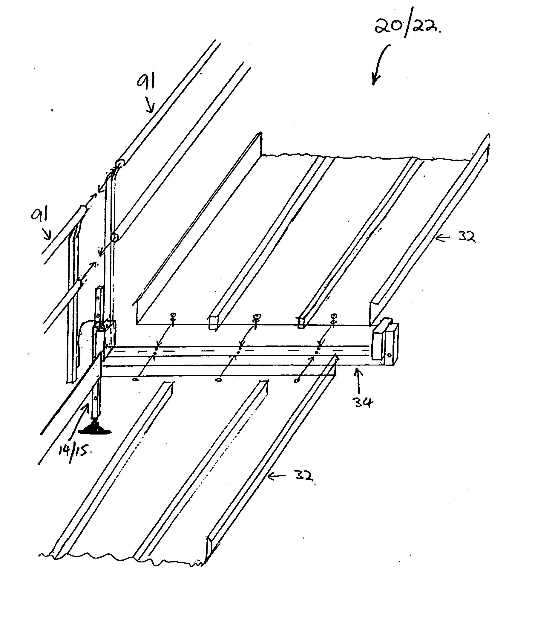
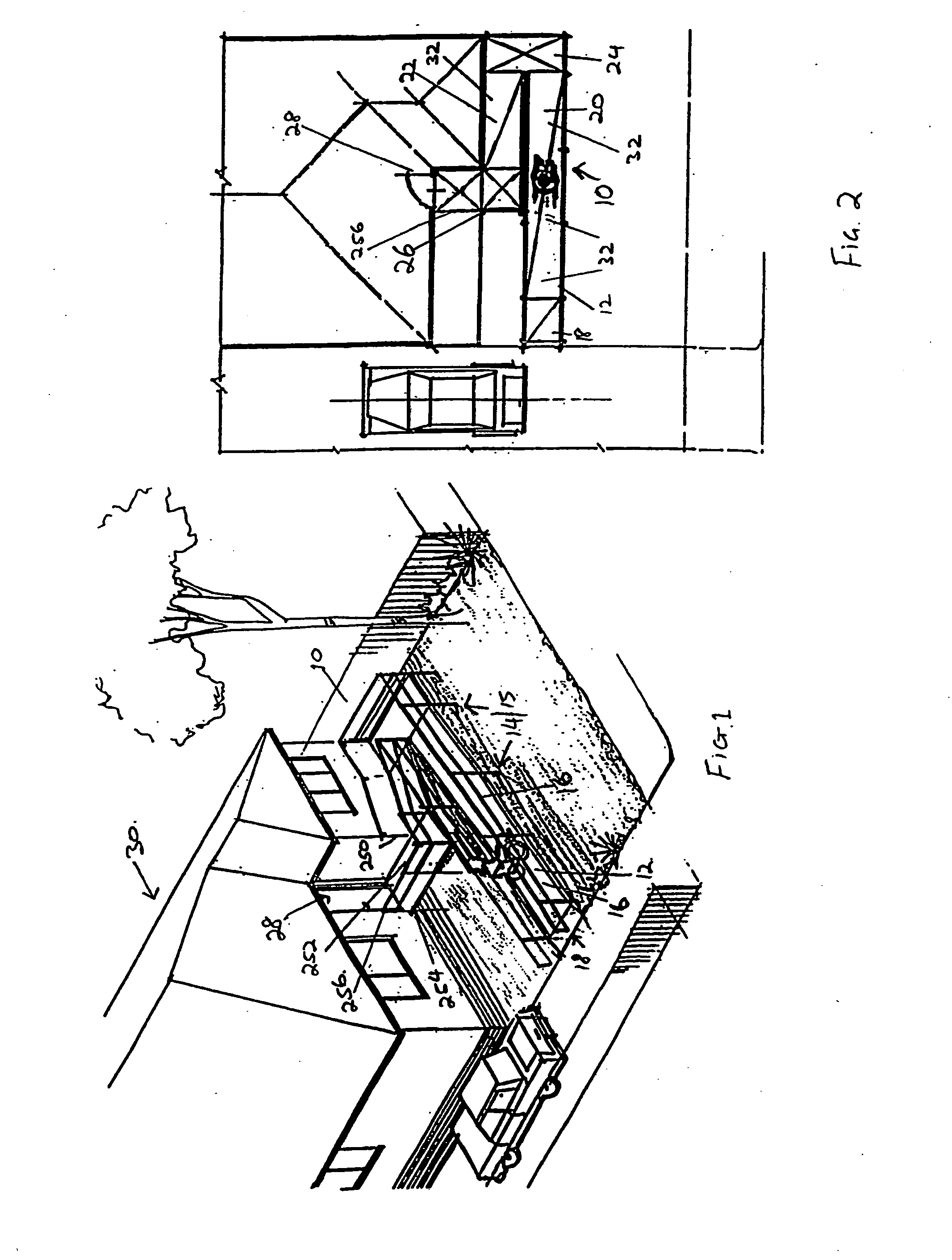
[0082]FIGS. 1 and 2 depict a modular ramp 10 formed of a number of prefabricated components which are described below. As will be clear from the description of the modular ramp 10, it will be readily apparent to a person skilled in the relevant art, that components forming the modular ramp 10 can be used, in a similar manner, to form a platform or walkway. In the case of a walkway, the height of the floor bearers are adjustable so that the floor surface is generally level, rather than inclined. In the case of a platform, the size of the floor components and the length of the floor bearers can be increased.

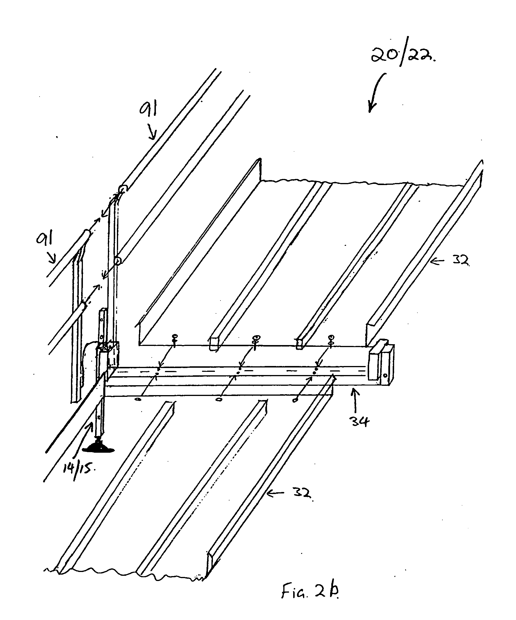
[0083] Referring to FIGS. 1 and 2, the modular ramp 10 generally comprises a raked floor 12, elongate members in the form of floor pillars 14 and 15, and handrails handrail 16, all formed of prefabricated components. The modular ramp 10 also comprises a number of different regions: an initial incline region 18; incline regions 20 and 22; a double landing 24 and a landing 26. The i...


PUM


Abstract

The present invention relates generally to a modular ramp (10) formed of prefabricated components. The modular ramp (10) includes a raked floor (12), elongate members in the form of floor pillars (14) and (15), and hand rails (16). The raked floor (12) is formed of a number prefabricated floor segments, an example of which are prefabricated floor panels (32) which extend between adjacent prefabricated floor bearers (34). The floor bearers (34) are supported by the floor pillars (14) and (15). The prefabricated floor bearers (34) have sleeves (56) and 58 attached at each end for respective receipt of the floor pillars (14) and (15). The pillars (14) and (15) are thus arranged for longitudinal movement relative to the sleeves such as (56) and locating pins (83) retain the pillars (14) or (15) relative to the sleeve (56).

Description

FIELD OF INVENTION [0001] The present invention relates to platforms, walkways or ramps and in particular to modular pre-built or temporary platforms, walkways and ramps. However, the present invention is not limited to temporary platform, walkways and ramp but also relates to permanent platforms, walkways and ramps. BACKGROUND TO THE INVENTION [0002] A large number of existing buildings do not include wheelchair access and as such there is a need to be able to modify existing buildings to include ramp access. While ramps can be retrofitted to buildings, they are typically designed for a specific building and therefore cannot usually be duplicated for other buildings. [0003] There is also a need for effective ramps for new buildings, and for cost effective platforms and walkways. [0004] Patent searches have revealed three patent specifications, namely U.S. Pat. No. 5,740,575, and Australian patent No. 577569 and associated Australian patent No. 589013, which disclose ramp kits compr...

Claims


Application Information

Patent Timeline
IPC IPC(8): E01D1/00A61G3/06E04F11/00E04F11/18E04G1/15E04G1/20E04G1/28E04G5/14E04G21/32E04G27/00
CPCA61G3/061E04F11/002E04F11/1865E04F2011/007E04G27/00E04G1/20E04G1/28E04G5/14E04G21/3204E04G1/152E04G21/3209
Inventor SUGGATE, TREVOR ROSS
Owner SUGGATE TREVOR ROSS
Learn More