
Foot guided shoe sole and footbed

a technology of shoe soles and footbeds, applied in the field of shoe soles, can solve the problems of inability of the inner layer to react, limited and altered ability of the structure to move along multiple planes, and essentially lost foot motion, and achieve the effect of a greater degree of flexing

Inactive Publication Date: 2006-04-20
ALINE SYST INC
View PDF39 Cites 17 Cited by
  • Summary
  • Abstract
  • Description
  • Claims
  • Application Information

AI Technical Summary

Benefits of technology

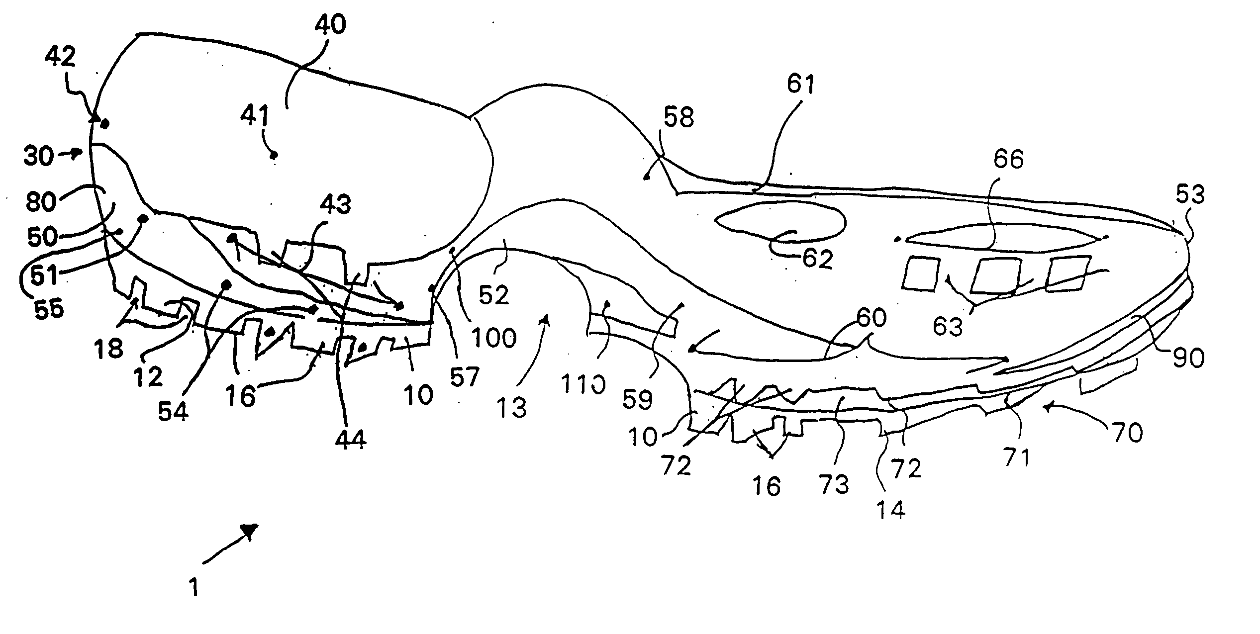
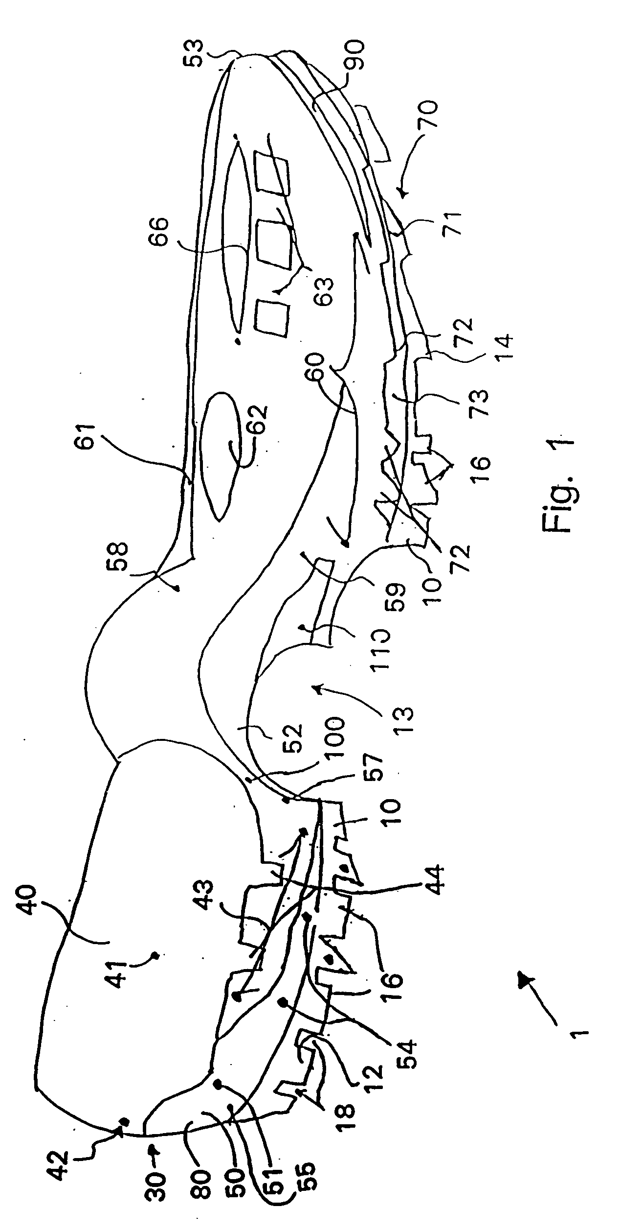
The present invention is about a shoe structure that helps to direct the forces between a person's foot and the shoe during a step. It includes an inner sole, a mid-sole, and a ribbon force transfer structure between the inner and mid-soles. The ribbon has many ribs that flex along its length and are positioned between the inner and mid-soles. This structure helps to transfer the person's weight from the heel to the toe of the shoe during a step, while also providing flexibility and comfort. The ribbon is designed to resist bending in one direction and allow flexing in another direction, which helps to direct the forces in a way that reduces impact and improves efficiency.

Problems solved by technology

The inner layer, however, is not structured to react to movement occurring within the foot and be guided by the foot during walking.
However, the ability of the structure to move along multiple planes is limited and altered by man-made footwear.
Thus, while the foot is in the air, the motions of the foot are, essentially, lost.

Method used


Image

  • Foot guided shoe sole and footbed
  • Foot guided shoe sole and footbed
  • Foot guided shoe sole and footbed

Examples


third embodiment

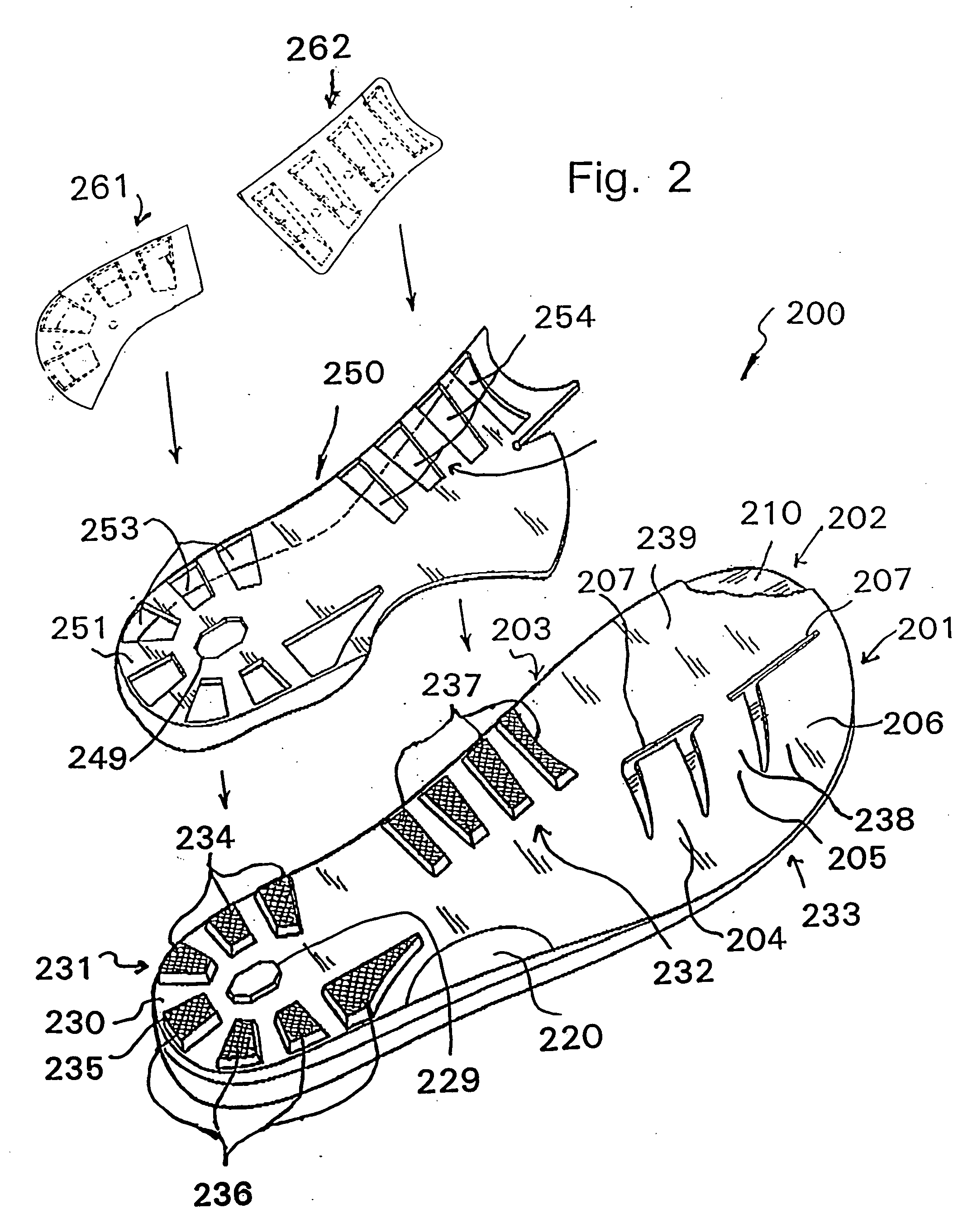
[0111] With reference to FIGS. 16-30, the reactive upper sole, according to the present invention will now be described. According to this embodiment, the reactive upper sole includes a foot bed 300 that is structured to be placed on top of a first frame assembly 40 and the second frame assembly forward portion 53. The foot bed 300 is an insert that is structured to cooperate with the e.g., and mid sole and an outer sole (not shown). The characteristics features of the foot bed 300 may be changed by changing the materials used for manufacture of the foot bed 300 and altering the number and / or location of the various components.

[0112] The foot bed 300 includes a plurality of folding directional levers 301, 302, 303. The first lever 301 extends longitudinally on the outer side of the forward portion of the sole. The second lever 302 extends longitudinally on the inner side of the forward portion. The third lever 303 extends, generally, perpendicular to a longitudinal axis of the foot ...

fifth embodiment

[0131] With reference to FIGS. 43-45, the reactive upper sole, according to the present invention will now be described. According to this embodiment, the reactive upper sole includes a foot bed 500 that is structured to function as the mid sole and may be used in combination with one or more frame assemblies as with the previous embodiments, e.g., the foot bed 50 may be placed on top of a first frame assembly and a second frame assembly forward portion. The foot bed 500 is an insert that is structured to cooperate with the outer sole. The characteristics features of the foot bed 500 may be changed by changing the materials used for manufacture of the foot bed 500 and altering the number and / or location of the various components.

[0132] The foot bed 500 includes a plurality of folding directional levers 501, 502, 503. The first lever 501 extends longitudinally on the outer side of the forward portion of the sole. The second lever 502 extends longitudinally on the inner side of the fo...


PUM


Abstract

A footwear sole structure for dynamically directing interacting forces between a user's foot and the footwear during a stride, including an inner sole located adjacent the user's foot, a mid-sole located between the inner sole and the footwear, and a rib ribbon force transfer structure located between the inner sole and the mid-sole wherein the rib ribbon includes a plurality of ribs spaced along and transversely to a spine axis and attached to a longitudinally extending spine. The rib ribbon resists flexing about an axis parallel to the spine axis and allows a relatively greater degree of flexing about an axis transverse to the spine axis and the rib ribbon is located along a path between the inner and mid-soles to dynamically direct the interacting forces between a user's foot and the footwear as the user's weight shifts from a heel to a toe position during a stride.

Description

CROSS REFERENCES TO RELATED APPLICATIONS [0001] The present application is a continuation in part of and claims benefit of co-pending U.S. patent application Ser. No. 10 / 246,176 filed Sep. 18, 2002 which in turn claims benefit of parent U.S. patent application Ser. No. 10 / 156,577 filed May 24, 2002, which claims benefit of parent PCT Patent Application Serial No. PCT / US02 / 05709 filed Feb. 20, 2002, U.S. Provisional Patent Application Ser. No. 60 / 323,298 filed Sep. 18, 2001, which claims benefit of Italian Patent Application Serial No. MT2001 T000351 filed Feb. 21, 2001.FIELD OF THE INVENTION [0002] This invention relates to shoe soles and, more specifically, to an inner shoe sole that is structured to react to movement by the wear's foot. BACKGROUND OF THE INVENTION [0003] Shoe soles are well known in the prior art. Modern shoe soles include many layers, e.g., an outer sole, an middle sole and an inner sole. Typically, there is a rubber outer layer that is structured to contact and ...

Claims


Application Information

Patent Timeline
Patent Type & Authority Applications(United States)
IPC IPC(8): A43B13/14A43B13/12
CPCA43B7/142A43B7/143A43B7/144A43B7/145A43B7/223
Inventor HAY, GORDON GRAHAMORR, KEITH M.CARROLL, DEREK
Owner ALINE SYST INC
Learn More