Power entry assembly for an electrical distribution system

a technology for power entry and electrical distribution, applied in the direction of coupling device connection, coupling device details, connection contact member materials, etc., can solve the problems of time-consuming and expensive process, difficult connection, and difficulty in installation, so as to achieve convenient and cost-effective

Inactive Publication Date: 2006-04-20
GROUP DEKKO
View PDF23 Cites 21 Cited by
  • Summary
  • Abstract
  • Description
  • Claims
  • Application Information

AI Technical Summary

Benefits of technology

[0013] An advantage of the present invention is that it provides a power entry assembly which easily and cost effectively provides both AC and DC interconnection between a power entry box and a distribution harness of an electrical distribution system.
[0014] Another advantage of the present invention is that it is configured for connection to the power entry harness connector of the distribution harness.
[0015] Yet another advantage is of the present invention is that it is configured for a “blind” connection to the power entry harness connector of the distribution harness.
[0016] Yet another advantage is of the present invention is that it has two different conductor carriers, one for AC conductors and one for DC conductors.
[0017] Yet another advantage of the present invention is that the two different conductor carriers have different outside textures which are tactile discernibly different, which allows an installer to correctly orient the power entry assembly relative to the distribution harness by feel alone (i.e., without visual contact).

Problems solved by technology

This process can be time consuming and expensive, as it generally requires highly skilled installation personnel.
Additionally, such an installation can be somewhat dangerous in that it requires the installation personnel to stand on ladders in the case of overhead wiring, or the like, and perform a multitude of tedious operations.
One of the problems associated with making electrical connection between the power entry box and the distribution harness is that the electrical distribution system may be an overhead system in which the connection is not easily made.
Yet further, the power entry harness connector of the distribution harness may have its access at least partially obscured by structural components which hold the distribution harness, thereby requiring a “blind” connection to the distribution harness by the installation personnel.

Method used


Image

  • Power entry assembly for an electrical distribution system
  • Power entry assembly for an electrical distribution system
  • Power entry assembly for an electrical distribution system

Examples


Embodiment Construction

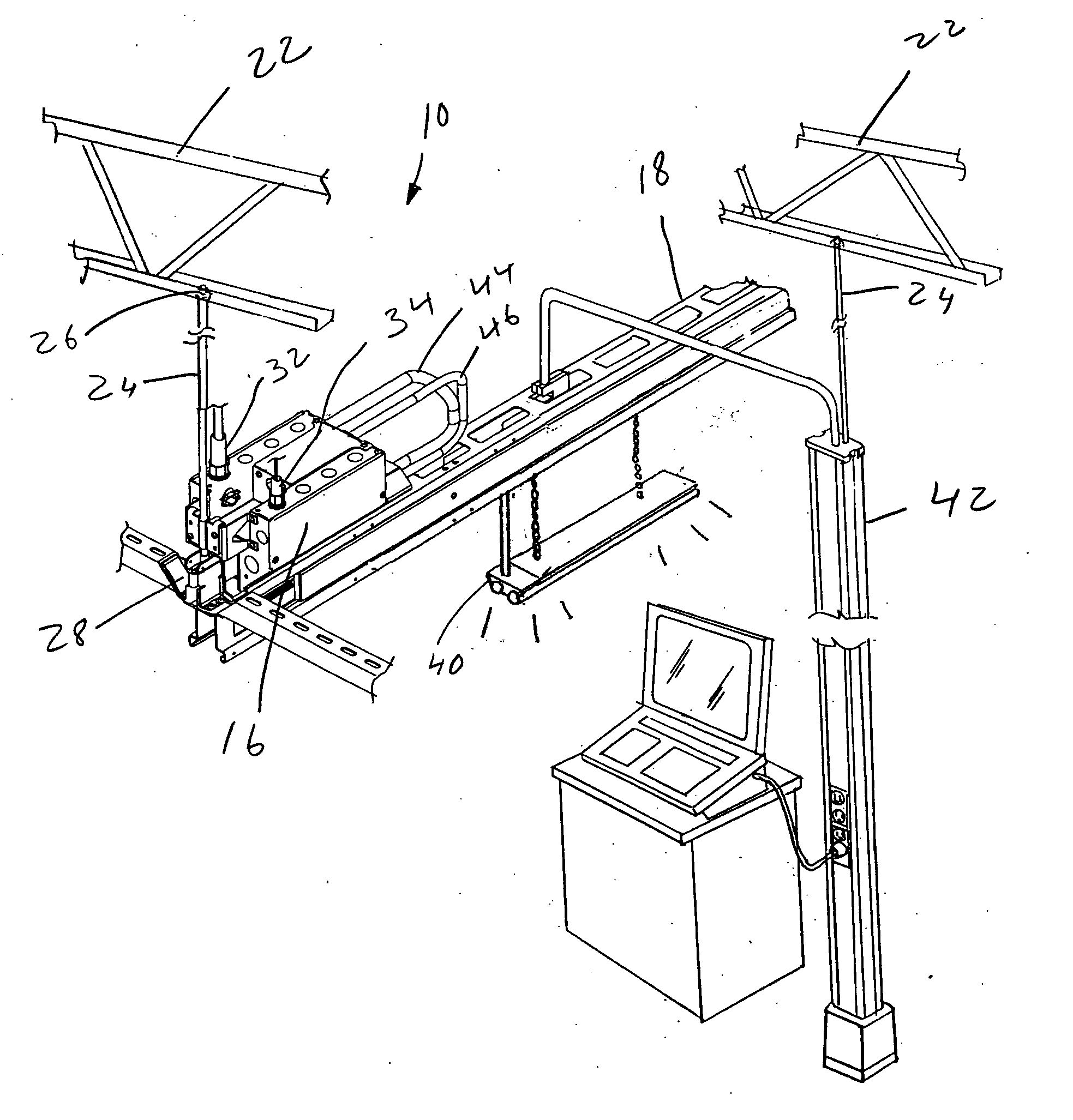
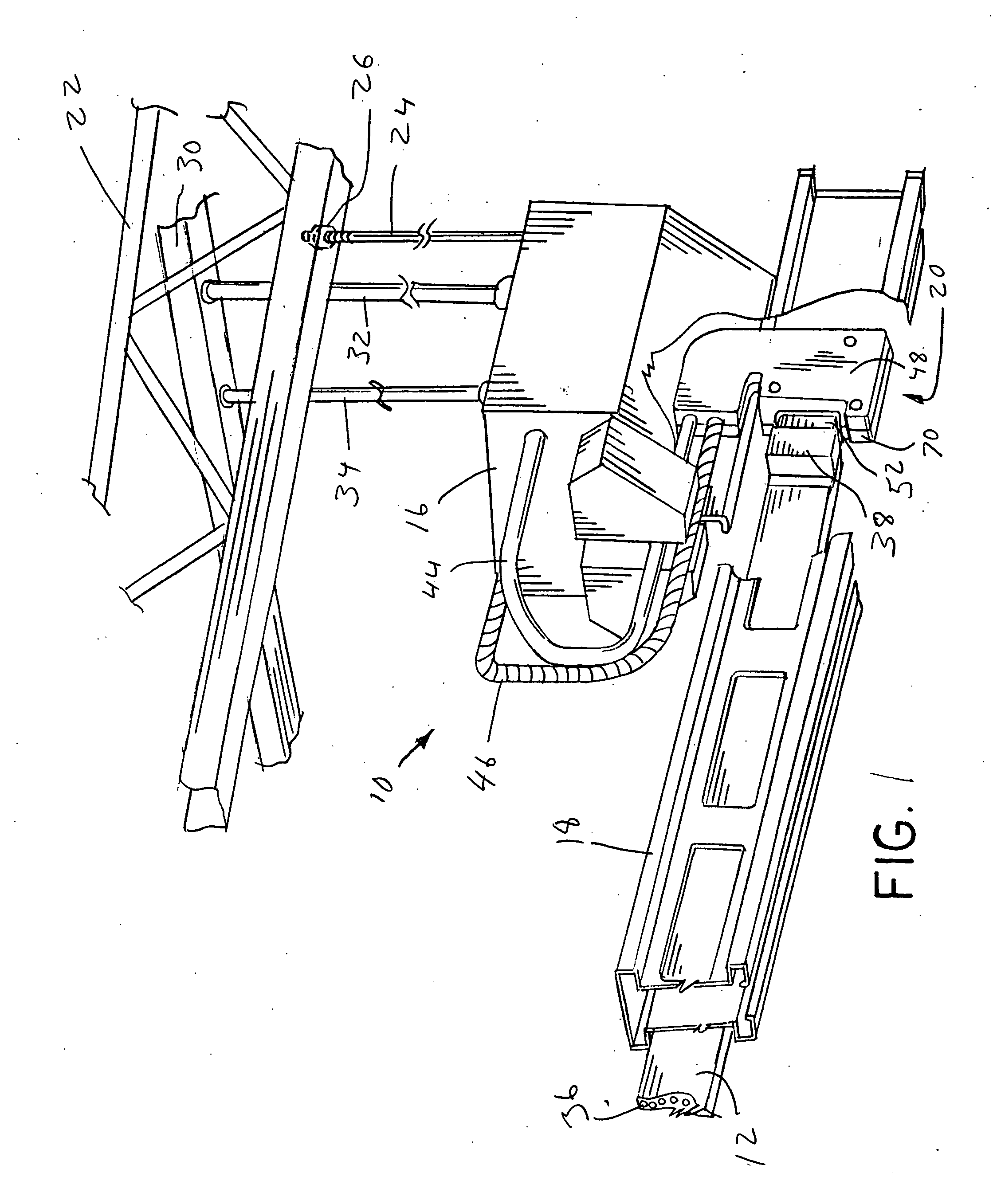
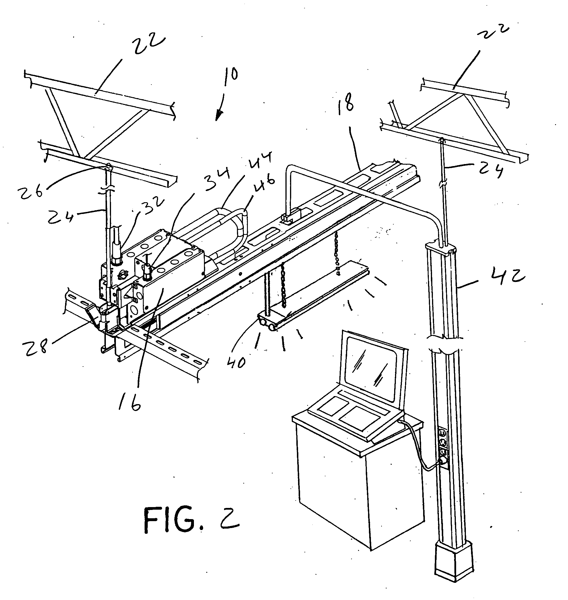
[0025] Referring now to the drawings, and more particularly to FIG. 1, there is shown an electrical distribution system 10 which generally includes an electrical distribution harness 12, a power entry box 16, a structural element 18 and a power entry assembly 20.

[0026] Structural element 18 can be attached to, and supported by, a ceiling joist 22 via threaded rods 24, fasteners 26 and hangers 28 (FIGS. 2 and 3). Raceway 30 can include AC and DC conductors (not shown), and other conductors or cables, which are passed through respective AC conduit 32 and DC conduit 34 to power entry box 16. Power entry box 16 is mounted to structural element 18. Power entry box 16 can have suitable internal elements such as bus bars, circuit boards, control elements, etc., to facilitate the routing and control of the AC and DC circuits from respective AC conduit 32 and DC conduit 34.

[0027] Electrical distribution harness 12 can include harness conductors 36 which can comprise either AC and / or DC cir...


PUM


Abstract

A power entry assembly for an electrical distribution system, the power entry assembly includes at least one conductor carrier and a housing connected to the at least one conductor carrier. The housing includes a first orientation relative to the at least one conductor carrier. A connector is connected to the housing at a second orientation, where the first orientation is approximately 180° from the second orientation.

Description

CROSS REFERENCE TO RELATED APPLICATIONS [0001] This is a non-provisional application based upon U.S. provisional patent application Ser. No. 60 / 618,730, entitled “POWER ENTRY”, filed Oct. 14, 2004.BACKGROUND OF THE INVENTION [0002] 1. Field of the Invention [0003] The present invention relates to an electrical distribution system, and, more particularly, to a power entry assembly for an electrical distribution system. [0004] 2. Description of the Related Art [0005] Conventional electrical distribution systems include a power service entry into a circuit breaker or fuse box, and then distribution of conductors from the circuit breaker or fuse box to electrical receptacles, lights, electrical machinery, and the like. In the case of commercial buildings, and in other situations, the conductors may be routed through an exposed ceiling, or walls, to be connected to lighting, and / or dropped to a lower level to connect into power receptacles or electrical controls which are easily accessib...

Claims


Application Information

Patent Timeline
Patent Type & Authority Applications(United States)
IPC IPC(8): H01R4/60
CPCH01R13/72
Inventor KONDAS, SHAWN J.
Owner GROUP DEKKO
Why Eureka
Try Eureka