Handle control provided with an angular position sensor

a technology of angular position sensor and handle, which is applied in the direction of mechanical control devices, instruments, cycle equipment, etc., can solve the problems of not being reliable, angular position sensor described, and not being used in automotive solutions on motorcycles, etc., and achieves the effect of convenient and cost-effectiv

Active Publication Date: 2010-05-27
MARELLI EURO SPA
View PDF8 Cites 19 Cited by
  • Summary
  • Abstract
  • Description
  • Claims
  • Application Information

AI Technical Summary

Benefits of technology

[0015]It is the object of the present invention to provide a handle control provided with an angular position sensor, which handle control is free from the above-described drawbacks and specifically which is easy and cost-effective to be implemented.

Problems solved by technology

In the automotive field, there are various solutions for implementing an acquisition system for detecting the position of the gas pedal; however, such automotive solutions may not be used on a motorcycle as they are too cumbersome and not rugged enough.
The angular position sensor described in patent U.S. Pat. No. 6,832,511B2 has the drawback of being not very reliable, because the use of a potentiometer arranged at one end of the handlebar is very problematic due to the high vibrations present in this area; in other words, a potentiometer provides for a sliding contact between one or more movable sliders and a fixed plate, and such a sliding contact is very sensitive to mechanical vibrations.
Such vibrations may negatively affect the reading provided by the potentiometer, because they may cause undesired, uncontrolled oscillations on the position of the potentiometer sliders, which cause a high degree of uncertainty on the measurement provided by the potentiometer; furthermore, over time, such vibrations may deteriorate the potentiometer thus determining early, unpredictable wear with negative potential impacts on the driver's safety.
The position sensors used in the handle control device of patent application WO2008010186A2 require the use of permanent magnets for determining the angular position of the handle; however, using permanent magnets is relatively unsafe, because the magnetic field generated by these permanent magnets may be affected in an undesired, unexpected manner by surrounding metal objects (e.g. metal rings carried by the driver's right hand or metal reinforcements inserted in a glove worn on the driver's right hand) with a consequent deterioration of accuracy and speed in reading the angular position of the handle.

Method used


Image

  • Handle control provided with an angular position sensor
  • Handle control provided with an angular position sensor
  • Handle control provided with an angular position sensor

Examples


Embodiment Construction

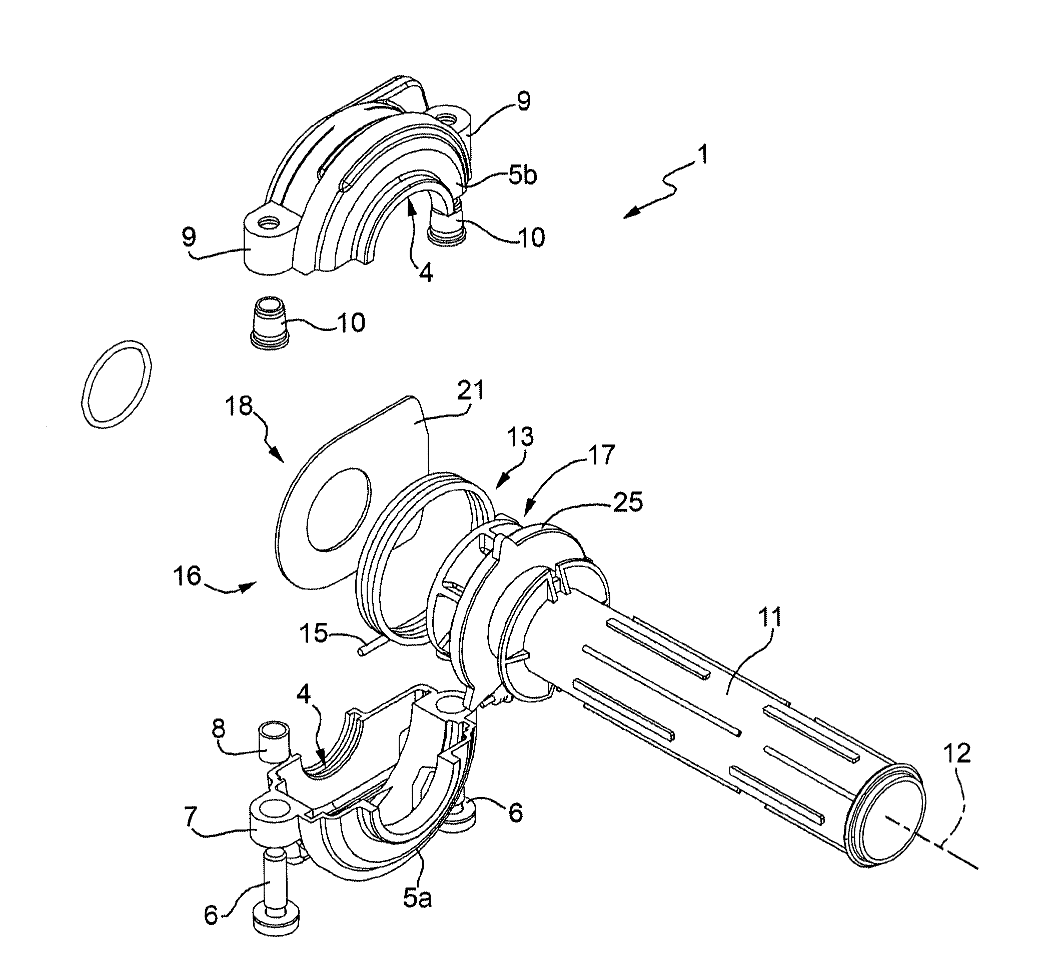
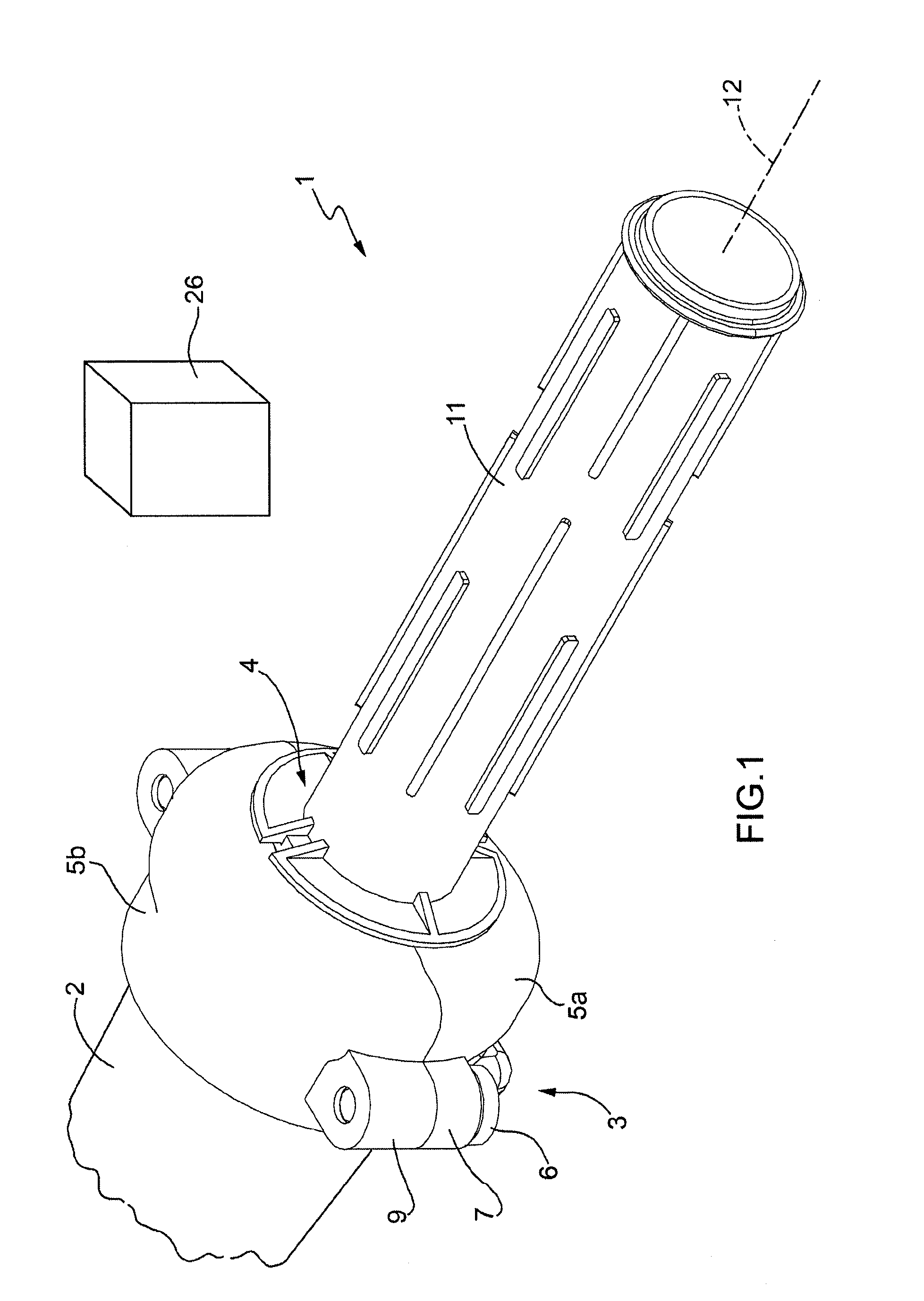
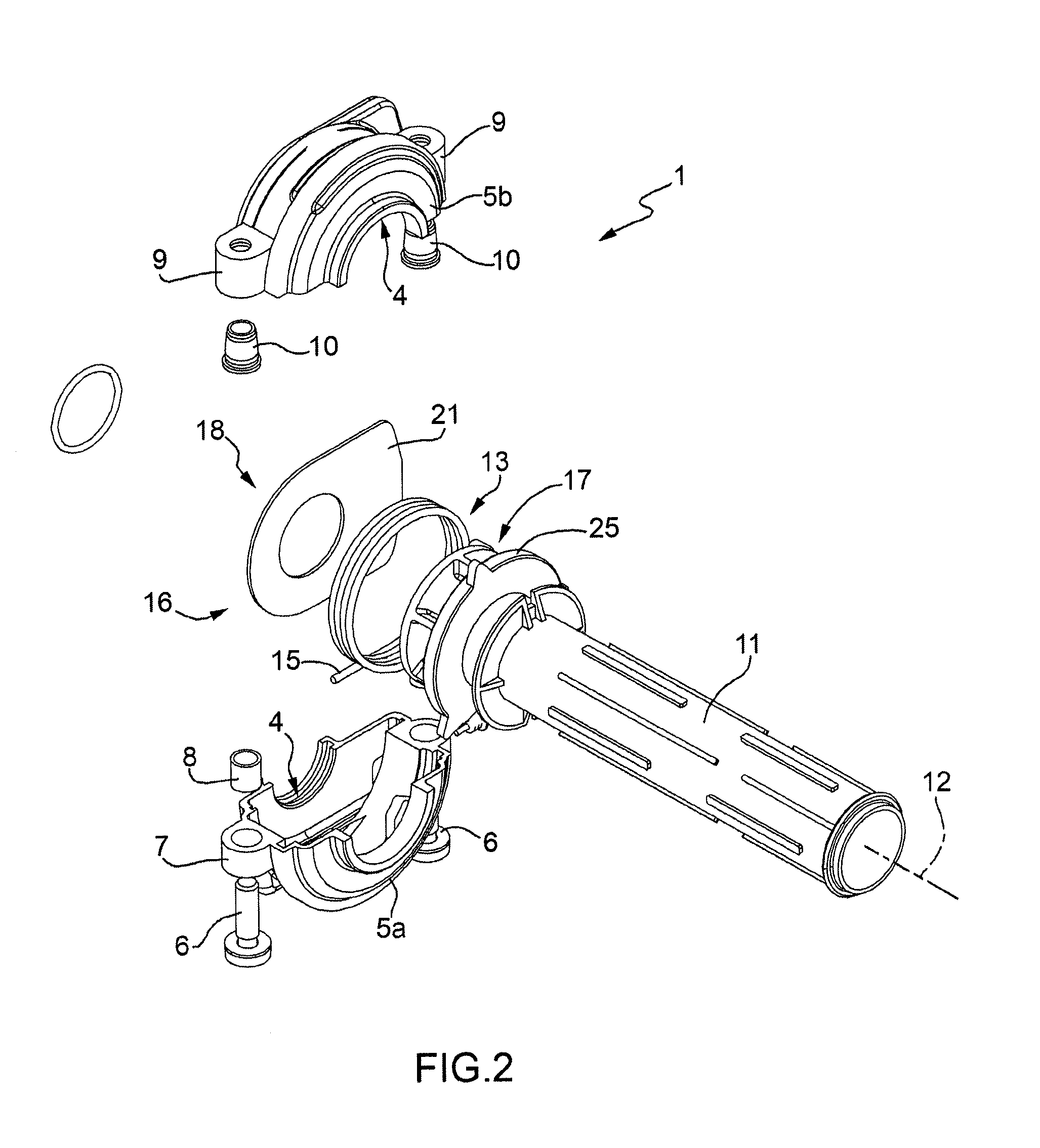
[0029]In FIG. 1, numeral 1 indicates as a whole a handle control which is mounted on a handlebar 2 of a motorcycle.

[0030]The handle control 1 comprises a supporting body 3, which is shaped as an annular shell, is provided with a central through hole 4 (shown in FIGS. 2 and 3) and is adapted to be fitted about the handlebar 2 to be rigidly fixed to the handlebar 2. As shown in FIG. 2, the supporting body 3 is made of molded plastic material and consists of two parts 5 which are reciprocally secured about the handlebar 2 and clamp onto the handlebar 2 by means of a pair of screws 6. Specifically, one part 5a has two slots 7, which define two respective through holes which are covered by two respective metal bushings 8 and are engaged by the screws 6; the other part 5b has two slots 9, which are aligned with the slots 7 of the part 5a, and define two respective blind holes which are covered by two respective threaded metal bushings 10 in which the screws 6 are screwed.

[0031]Furthermore...


PUM


Abstract

A handle control provided with: a supporting body, which is provided with a central through hole and is adapted to be fitted about a handlebar to be rigidly fixed to the handlebar; a twist grip, which has a tubular shape, is rotationally carried by the supporting body and is centrally perforated to be fitted about the handlebar so as to rotate with respect to the handlebar; and an angular position sensor, which is adapted to read the angular position of the twist grip; the angular position sensor has at least one rotor, which is supported by the twist grip to rotate along with the twist grip and is adapted to influence an electric field; and at least one reader, which is carried in a stationary position by the supporting body, is arranged close to the rotor, and is suitable for a contactless and remote reading of the orientation of the rotor.

Description

CROSS-REFERENCE TO RELATED APPLICATION[0001]This application claims the priority of European Patent Application No. 08425761.7 filed Nov. 26, 2008 and European Patent Application No. 09160703.6 filed May 19, 2009, the subject matter of which is incorporated herein by reference.TECHNICAL FIELD[0002]The present invention relates to a handle control provided with an angular position sensor.[0003]The present invention is advantageously applied to a motorcycle, to which explicit reference will be made in the following description without hence loosing in generality.BACKGROUND ART[0004]A traditional motorcycle comprises a handle control (conventionally the grip on the right of the handlebar), which is rotationally mounted and mechanically connected to an engine control which adjusts the generation of the driving torque. Normally, the handle control is connected to the engine control by means of at least one Bowden-type metal cable, which is inserted into an external sheath to slide with r...

Claims


Application Information

Patent Timeline
Patent Type & Authority Applications(United States)
IPC IPC(8): G05G1/08
CPCB62K23/04Y10T74/20396F02D11/10F02D11/02
Inventor BALDASSARI, ANDREAPICIOTTI, ROBERTOCANNONE, DOMENICOXELLA, MAURIZIO
Owner MARELLI EURO SPA
Why Eureka
Try Eureka