Internal heat exchanger with calibrated coil-shaped fin tube

a heat exchanger and coil-shaped technology, which is applied in indirect heat exchangers, lighting and heating apparatuses, transportation and packaging, etc., can solve the problems of large flow loss, large problem of low pressure side, and inability to manufacture easily and cost-effectively, and achieve less flow loss. , the effect of reducing the amount o

Inactive Publication Date: 2007-12-20
VISTEON GLOBAL TECH INC
View PDF20 Cites 21 Cited by
  • Summary
  • Abstract
  • Description
  • Claims
  • Application Information

AI Technical Summary

Benefits of technology

[0018] An objective of the invention is to provide an internal heat exchanger with accumulator for refrigerant circuits, whereby the above mentioned disadvantages of the state-of-the-art the heat exchangers are eliminated, which is configured to be easily and cost-effectively manufactured, which provides a large heat transmission area for the low-pressure flow, which creates less flow losses of the low-pressure flow, and which avoid bypass flows

Problems solved by technology

For thermodynamic reasons, the low pressure side is considerably more problematic than the high-pressure side as to the pressure loss and heat transmission.
The disadvantage of this internal heat exchanger with a high-pressure pipe is that the refrigerant circulating countercurrently produces pressure losses on the low-pressure side that are too high and the available heat exchanger surface is too small.
However, manufacture of an internal heat exchanger with bundled smooth pipes is expensive and the produced heat transmission packets are difficult to reproduce as to the exact determination of the gaps decisive for the flow cross-sectional area.
On the low-pressure side, however, the pressure loss must be kept comparatively low for thermodynamic reasons, which requires relatively wide cross-sections.
This construction, however, has some design disadvantages.
Then, low-pressure bypass flows will pass through these annular gaps, significantly impairing the efficiency of the internal heat exchanger.
If the fin heads do not bear against the annular gap surfaces, then under normal vehicle vibration conditions the tube coil starts to vibrate, continuously beating against the container walls, which leads to considerable noise development.
If the fin tubes themselves and the tube coils are manufactured true to size in order to avoid annular gaps between the fin heads and the coil walls, at a very great expense, considerable problems are created particularly in series production when the components are assembled.
Assembling under the condition of such a little allowance between the tube coils and annular gaps is additionally made even more difficult in that the tube coils with the fines get caught on each other when they are axially assembled.
Adapting the coil diameter, for example, by manually rotating the tube coil during the assembling process gets nearly impossible.
Whether there is a gap or not between the fin heads and the container walls, due to the natural vehicle vibrations, the fins can produce notches in the container walls.
The notches may possible lead to failure of the component.

Method used


Image

  • Internal heat exchanger with calibrated coil-shaped fin tube
  • Internal heat exchanger with calibrated coil-shaped fin tube
  • Internal heat exchanger with calibrated coil-shaped fin tube

Examples


Embodiment Construction

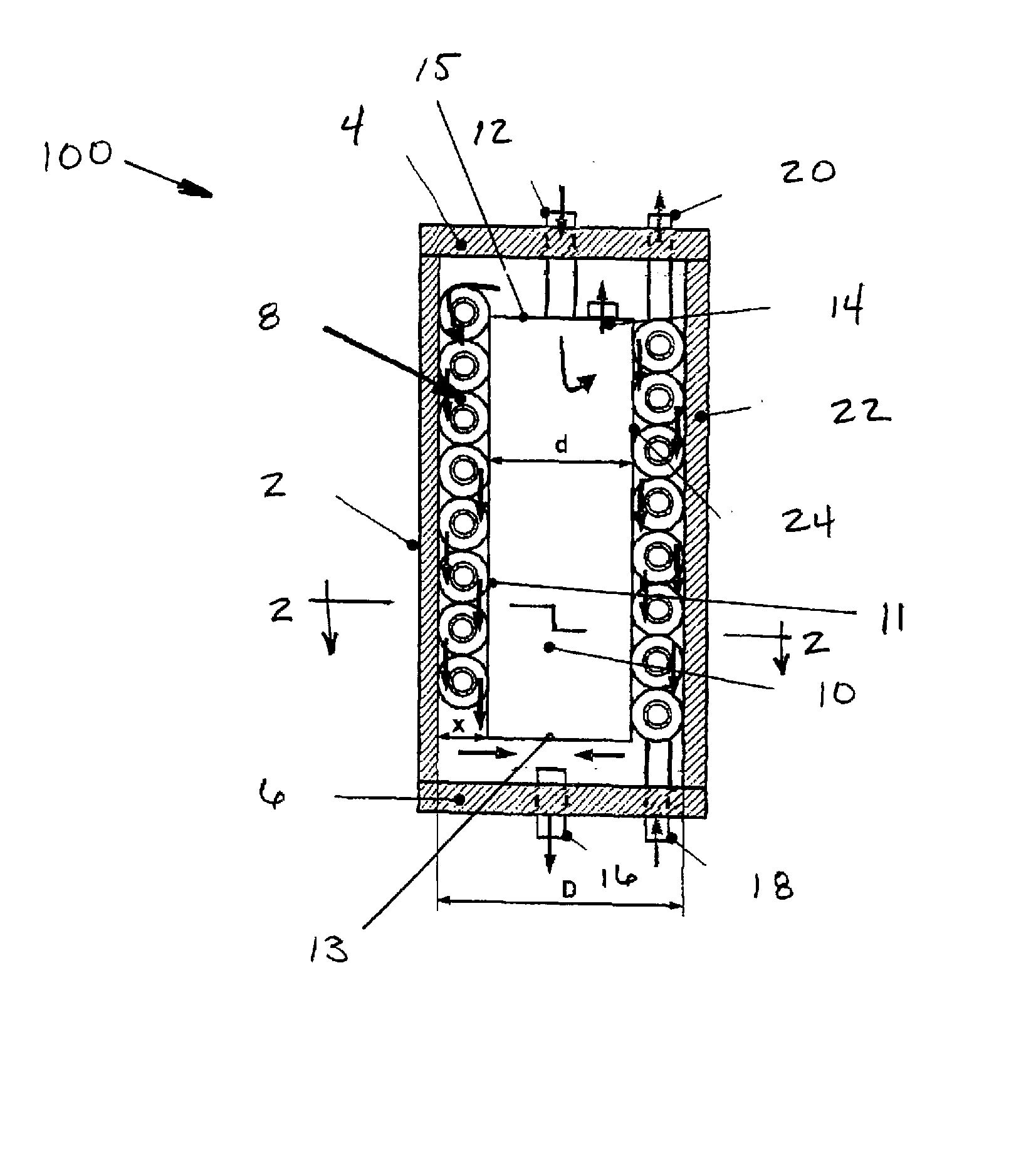
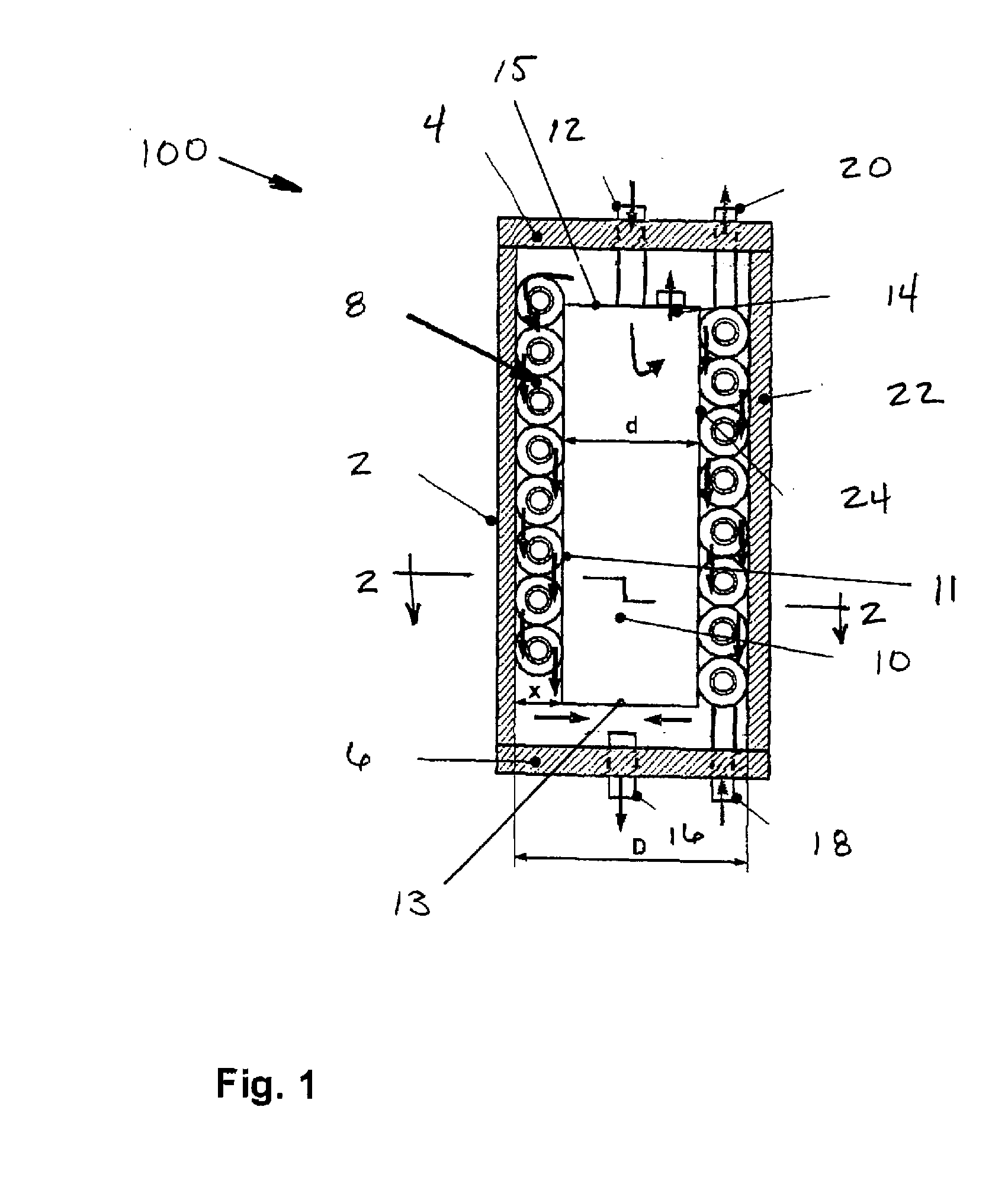
[0041] In FIG. 1 an internal heat exchanger 100 with a coil-shaped fin tube is shown; the heat exchanger 100, together with an accumulator 10 forming a unit. The internal heat exchanger 100 includes a casing 2, which is preferably cylindrical, particularly circular-cylindrical. The casing 2 is limited by a top cover plate 4 and a bottom cover plate 6. Integrated into the top cover plate 4 is a low-pressure inlet 12 and a high-pressure outlet 20. Integrated into the bottom cover plate 6 is a low-pressure outlet 16 and a high-pressure inlet 18. The accumulator 10 is provided concentrically in the interior of the heat exchanger 100 and is in the form of a cylinder. A side wall 11 of the accumulator 10 is closed at the bottom by a bottom cover plate 13 and at the top by a top cover plate 15. In the top cover plate 15, there is provided an opening for the low-pressure inlet 12 next to an opening configured as overflow 14. The refrigerant, at high pressure, passes through the coil-shaped ...


PUM


Abstract

An internal heat exchanger unit for use in refrigerant circuits of automotive air conditioning systems. The internal heat exchanger includes a casing within which is located an accumulator, spaced thereapart so as to define a gap between the two components. Located within the gap is a coil-shaped fin tube. The fins of the fin tube include bend end portions at spaced apart locations about the fins, and the bent end portions defining an outer dimension of the fins that substantially corresponds to the gap width.

Description

BACKGROUND [0001] 1. Field of the Invention [0002] The invention relates to an internal heat exchanger with a calibrated coil-shaped fin tube, which together with a refrigerant accumulator, forms a unit used in refrigeration circuits of the air conditioning of automotive vehicles. [0003] The combined accumulator with internal heat exchanger combines the functionalities of both components in one unit, a combined component. The combined component is used preferably in mobile R744-refrigeration plants. Compared to the single components, the compact combined component adapts better to the limited space in the engine compartment. It is also advantageous as to costs for the general system of the mobile refrigeration plant. [0004] 2. Related Technology [0005] In a refrigeration machine or heat pump, the accumulator is arranged downstream of the evaporator and is intended to take refrigerant filling quantities varying due to varying operation conditions, thereby holding out a refrigerant re...

Claims


Application Information

Patent Timeline
Patent Type & Authority Applications(United States)
IPC IPC(8): F28F9/22
CPCB60H1/00328B60H1/00492F25B9/008F25B40/00F25B43/006F28F2240/00F25B2400/051F25B2500/18F28D7/024F28F1/24F25B2309/061
Inventor KOSTER, STEPHANHECKT, ROMANKLOTTEN, THOMASFIDLER, ZDENEKBARTOS, PAVEL
Owner VISTEON GLOBAL TECH INC
Why Eureka
Try Eureka