
Disc Brake, Brake Actuation Mechanism For Such A Disc Brake And Method For Brake Adjustment

a disc brake and disc brake technology, applied in the direction of actuators, slack adjusters, brake elements, etc., can solve the problems of counter-torque, failure to meet the expected clamping force, further heat generation, etc., to reduce the target clearance, reduce the stroke, and increase the elasticity of the caliper

Active Publication Date: 2016-01-21
HALDEX BRAKE PROD AB
View PDF9 Cites 21 Cited by
  • Summary
  • Abstract
  • Description
  • Claims
  • Application Information

AI Technical Summary

Benefits of technology

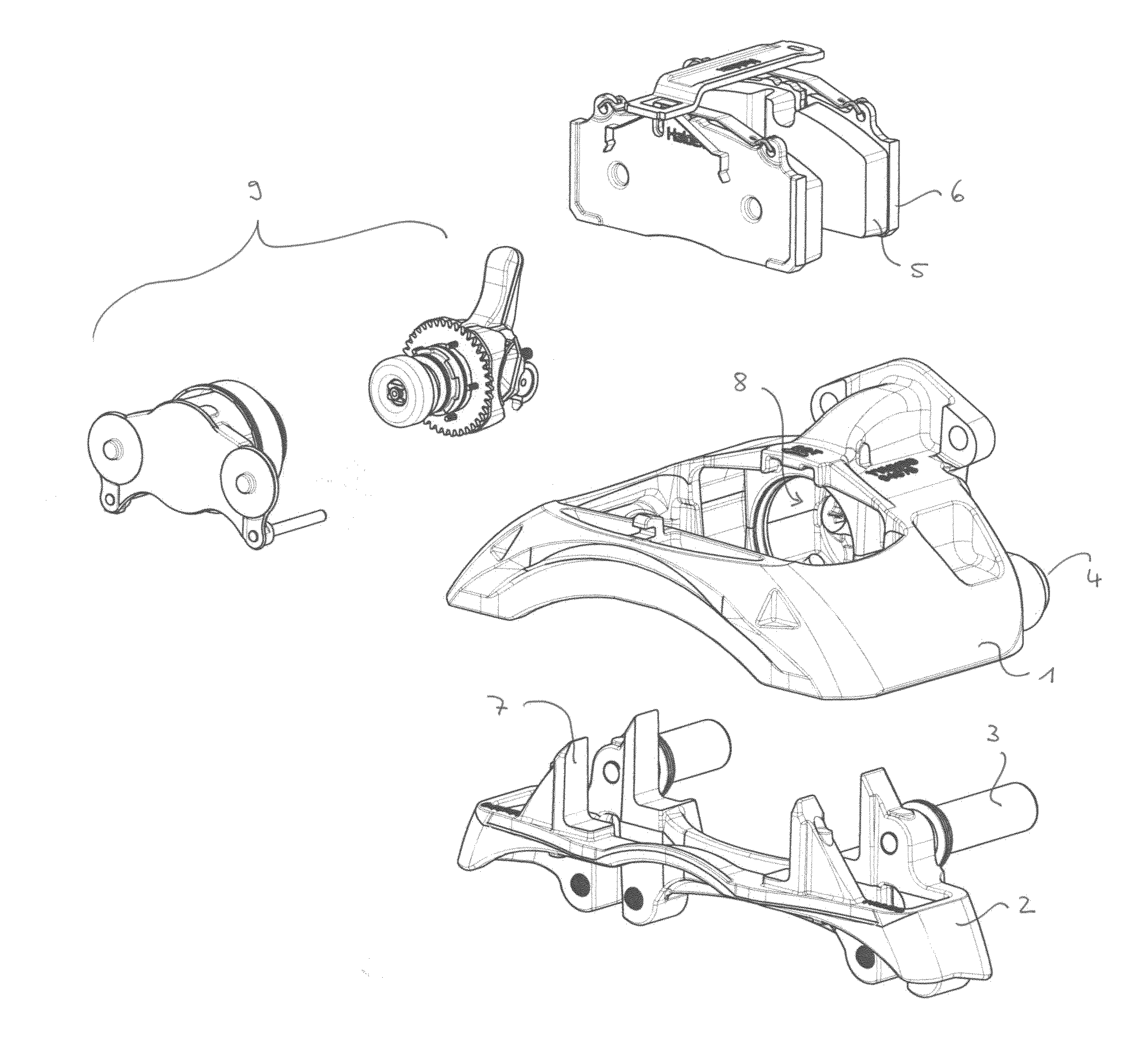
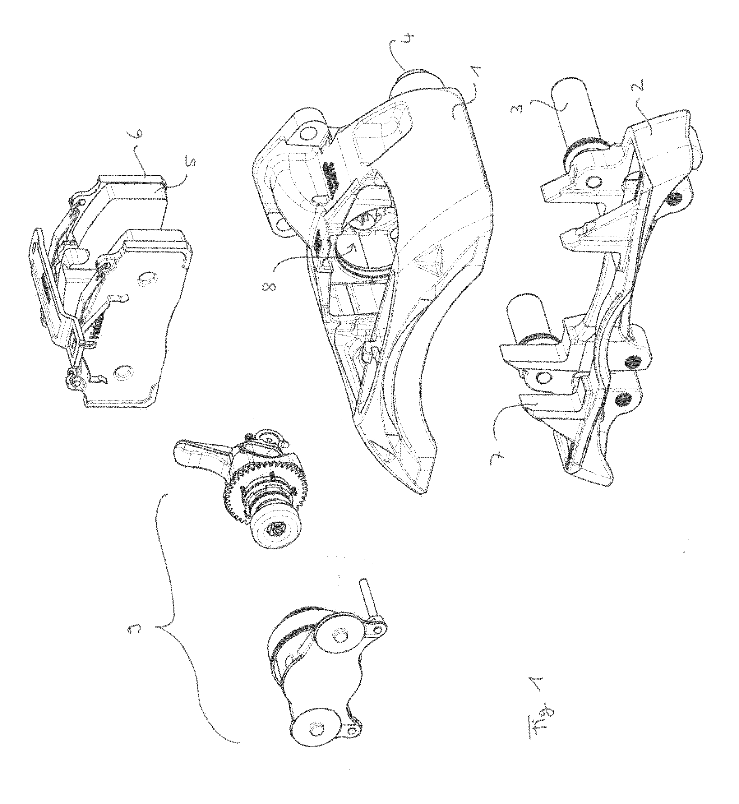
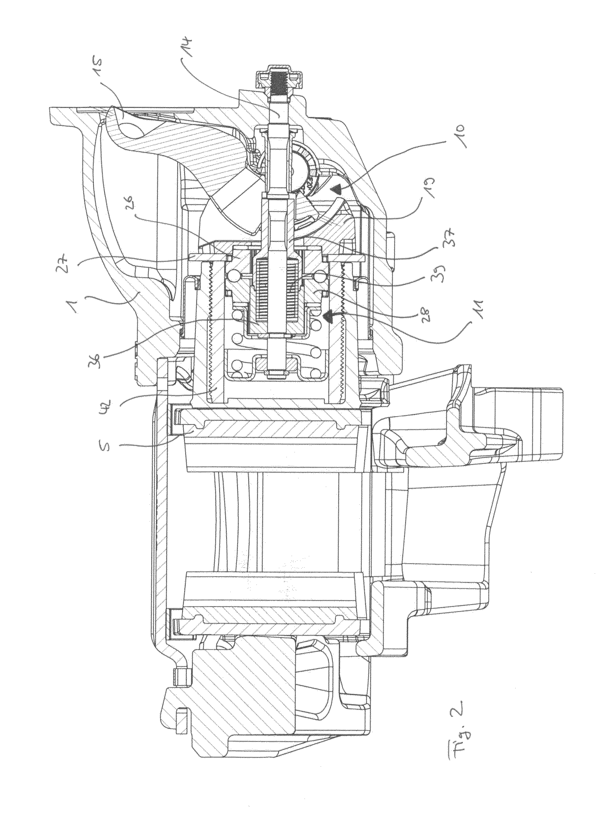
The present invention is a brake system that includes a disc brake and a brake actuation mechanism with an adjuster. The purpose of this adjuster is to compensate for possible wear by adjusting the clearance during brake actuation and also to prevent dragging by increasing the clearance. The adjustment mechanism is designed to be space-efficient, lightweight, easy to assemble, and manufacturable in a cost-effective way. Additionally, an adjustment method is provided that takes into account the risk of dragging and is independent of the wear-induced clearance.

Problems solved by technology

This torque is transmitted from the rotatable lever over an one-way clutch in its driving direction and limited by a torque limiting clutch slipping or overrunning when the rotational resistance between the threaded parts rises due to the axial force, which is built up when the brake pad contacts the brake disc, thereby creating some kind of counter-torque.
Namely, if the friction linings do wear to such an extent that the running clearance is greater than the target clearance, the existing running clearance between the brake pad and the brake disc is taken up and the further additional movement of the brake pad towards the brake disc, which results from and thus corresponds to the actually existing excessive lining wear, causes the clutch to rotate, which rotation will advance the brake pad towards the brake disc.
In addition it is provided with some kind of safety margin which could take up some excessive slack without reaching its maximum limit, which in turn would result in failure to meet the expected clamping force.
One major drawback upon brake operation is that the brake pad and the brake disc will notably expand due to the excessive heat generation which could result in that the contact between these components, especially after an immediate consecutive braking, cannot be completely dissolved, leading to dragging and thereby further heat generation and extremely large wear.
Nonetheless, such approach seems to be not an optimum solution for achieving the best possible utilization of the available actuator stroke.
Namely, providing the desired safety margins to avoid the risk of dragging as described above in turn comes with a large actuator and / or stiff and by that heavy caliper, which generally is undesired both with respect to fuel savings, vehicle handling and manufacturing costs.
Such design, however, proves to be technically complicated, costly to produce and moreover sensitive to disturbances of all kinds.

Method used


Image

  • Disc Brake, Brake Actuation Mechanism For Such A Disc Brake And Method For Brake Adjustment
  • Disc Brake, Brake Actuation Mechanism For Such A Disc Brake And Method For Brake Adjustment
  • Disc Brake, Brake Actuation Mechanism For Such A Disc Brake And Method For Brake Adjustment

Examples


first embodiment

[0148]FIG. 7a shows an actuation mechanism 62 including a mechanical adjustment mechanism according to the invention. FIG. 7b is a cross-section along K-K of FIG. 7a. Furthermore, FIG. 8 shows an explosive view of this design.

[0149]The rod 14 comprises a thread 63 at its end facing the brake disc. Onto this thread 63 a nut 64 is screwed which thereby encloses a distance sleeve 65 between it and the internal holding sleeve 36. Surrounding the hollow shaft 37 and the internal holding sleeve 36 is a first clutch ring 66, which is rotationally connected to the gear wheel 27 by a splined connection and supported against the force transmitting element 19 by a bearing 67. The first clutch ring 66 attaches to a second clutch ring 68, which thereby forms a friction clutch between these rings 66 and 68.

[0150]Between the second clutch ring 68 and the internal holding sleeve 36 a rolling guidance 69 is arranged, which provides a radial rotational connection and at the same time a low friction s...

fourth embodiment

[0174]A further embodiment of a brake actuation mechanism according to the invention is shown in FIGS. 13-14; FIG. 13a is a cross-section along I-I, FIG. 13b is a cross-section along Z-Z and FIG. 13c is a cross-section along X-X of FIG. 13; FIG. 14 is an explosive view of such

[0175]The brake actuation mechanism 94 including an adjustment mechanism shown therein comprises a roller-ramp clutch with a first clutch ring 95, being supported against the force transmitting element 19 via bearing 32, and a second clutch ring 96 enclosing a roller cage 97 with rollers 98 being received in ramp surfaces 99 of both clutch rings 95, 96.

[0176]Similar as in the previous embodiment, the second clutch ring 96 is radially supported against the internal holding sleeve 36 by a rolling guidance 100 providing radial rotational connection and low friction axial sliding between these components. Axially, the second clutch ring 96 is supported against a radial flange of a sleeve 101 via a bearing ring 102....

sixth embodiment

[0193]FIG. 17 illustrates a brake actuation mechanism according to the invention, which is an alternative to the previous embodiment.

[0194]The brake actuation mechanism 118 including the adjustment mechanism comprises at the end facing the brake disc a distance ring 119, basically made as an one piece of the outer ring 116 and the distance sleeve 115 of the previous embodiment. The distance ring 119 comprises a conically shaped outer recess 120 at the side of the external holding sleeve 35. The shaped outer recess 120 of the distance ring 119 is encased by the second wrap spring 117.

[0195]The angular slack Ai in this design in fact is achieved and arranged as the reduction of the outer diameter of the distance ring 119 axially most close to the internal holding sleeve 36. A change in torque direction from slipping to gripping direction at brake release will force the second wrap spring 117 to contract the turns of its wires into a smaller diameter before they make a firm grip and st...


PUM


Abstract

A disc brake including a brake actuation mechanism and an adjustment mechanism, which is configured to provide, in addition to a reduction of the clearance between a brake pad and a brake disc during brake application, a further increase of the clearance during brake release motion with a value, which may be smaller, equal or larger than the previous clearance reduction. The brake actuation mechanism for that purpose could provide a different regulator unit. Moreover, the invention suggests a method for adjusting the clearance between a brake pad and a brake disc providing a clearance increase during brake release motion, accordingly.

Description

FIELD OF THE INVENTION[0001]The present invention relates to a disc brake, in particular for a utility vehicle, and to a brake actuation mechanism of such a disc brake. Furthermore, the invention refers to a new kind of method for brake adjustment.BACKGROUND OF THE INVENTION[0002]In this connection the invention shall include disc brakes which either comprise a sliding caliper or a fixed caliper, which overlap one or more brake discs. Mainly but not exclusively the invention relates to disc brakes with lining sections of the spot-type.[0003]Disc brakes, in particular for heavy load trucks, are known with different configurations, both with respect to the type of the actuation mechanism, with respect to the way of the transmission of the braking or clamping force onto one or several brake discs and with respect to the type of the adjustment for compensating the wear of the brake pad and / or the brake disc as well as in this context with respect to the type of the adjustment of the run...

Claims


Application Information

Patent Timeline
Patent Type & Authority Applications(United States)
IPC IPC(8): F16D55/2265F16D65/66F16D65/00
CPCF16D65/66F16D2055/0016F16D65/0068F16D55/2265F16D65/18F16D65/567F16D2125/28
Inventor SANDBERG, STEFAN
Owner HALDEX BRAKE PROD AB
Learn More