System and method for compensating for potential and current transformers in energy meters

a technology of energy meters, which is applied in the field of system and method for compensating potential and current transformers in meters for measuring energy, can solve the problems of nonlinear errors introduced by current transformers, affecting the accuracy of measurements, and introducing errors into measurements

Active Publication Date: 2006-04-20
ELECTRO INDUSTRIES GAUGE TECH
View PDF9 Cites 84 Cited by
  • Summary
  • Abstract
  • Description
  • Claims
  • Application Information

AI Technical Summary

Problems solved by technology

The sensors are current and/or voltage (potential) transformers, which introduce errors into the measurements in addition to errors introduced by other sources, such as the meters themselves.
Furthermore, errors introduce...

Method used


Image

  • System and method for compensating for potential and current transformers in energy meters
  • System and method for compensating for potential and current transformers in energy meters
  • System and method for compensating for potential and current transformers in energy meters

Examples


Embodiment Construction

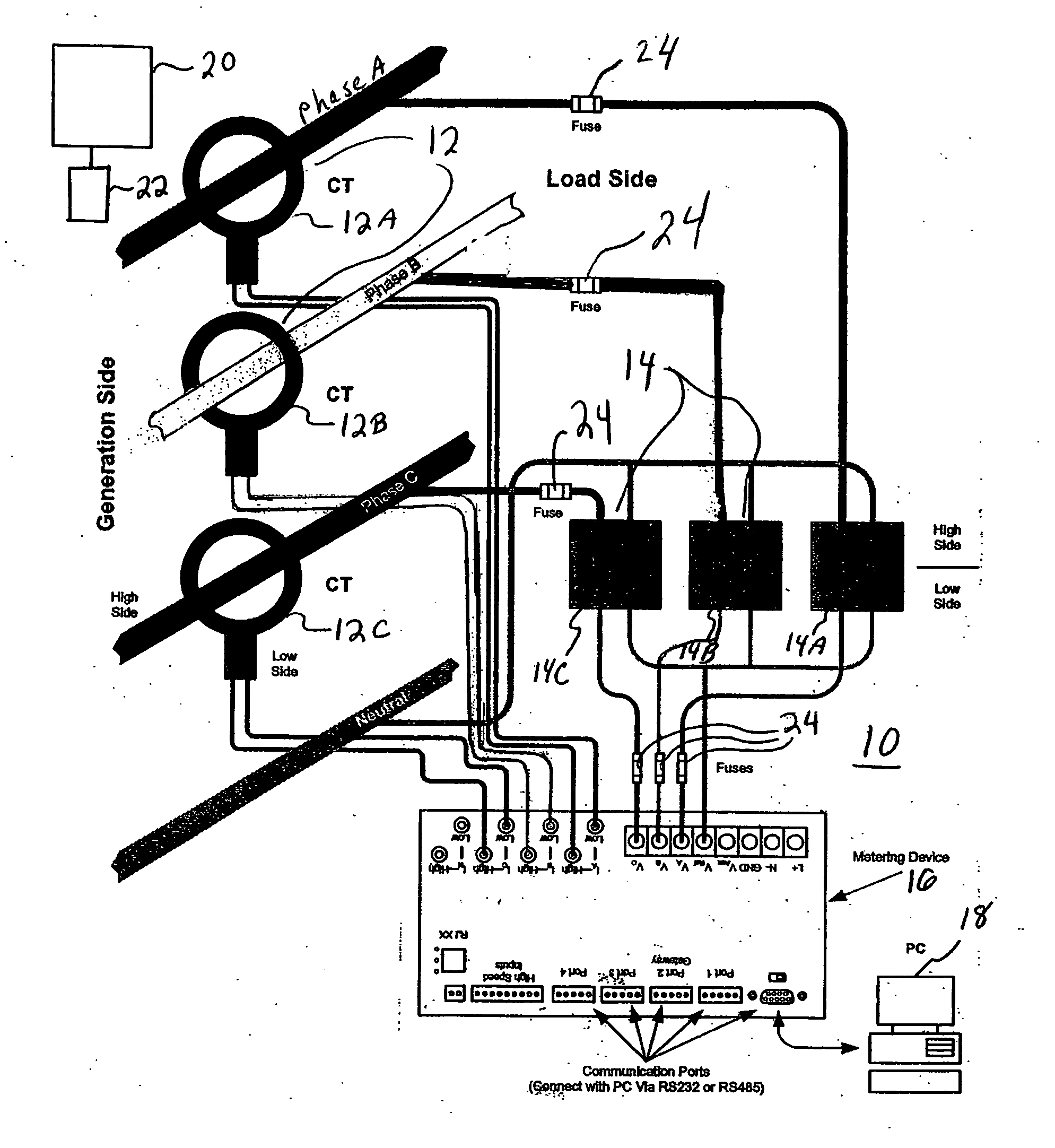
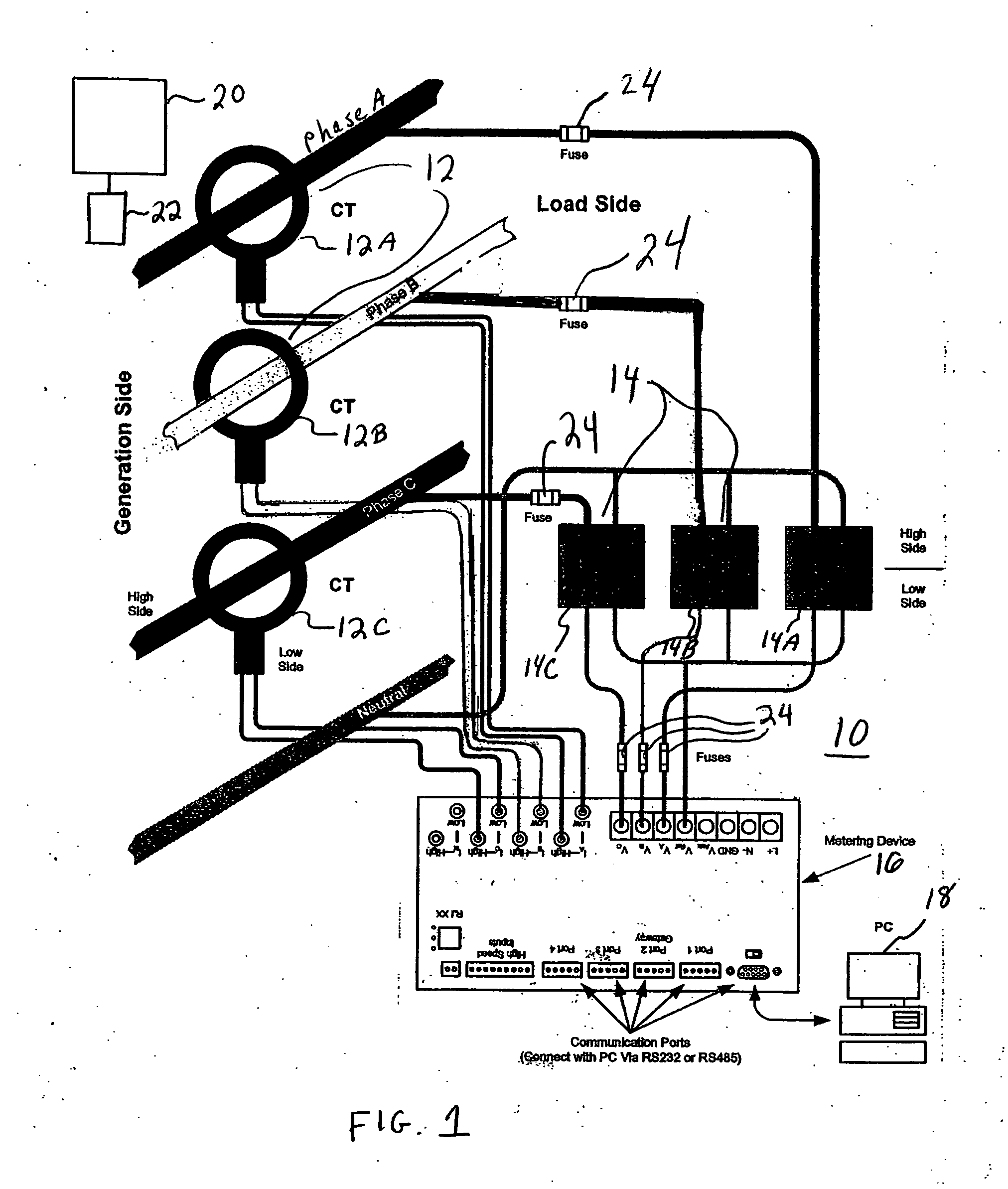
[0024] Referring now to the drawings wherein like reference numerals identify similar structural elements, there is illustrated in FIG. 1 a metering system 10 for metering power provided to the system 10 in at least one power line having at least one phase, and typically in three power lines having three respective phases, phases A, B and C. The respective power lines corresponding to phases A, B and C (wherein the power lines are herein referred to as phases A, B and C, respectively) pass through at least one instrument transformer, including current transformers (CTs) 12 and optionally potential (voltage) transformers (PTs) 14, where CTs 12A, 12B and 12C correspond to the phases A, B and C, respectively, and PTs 14A, 14B and 14C correspond to the phases A, B and C, respectively. The signals output by the CTs 12 and the PTs 14 (e.g., when PTs 14 are provided) are provided to an energy meter device 16 which is in wired or wireless communication with a processing device 18. In accord...


PUM


Abstract

A meter device for measuring electrical energy is provided. The meter device includes circuitry for measuring at least one parameter of electrical energy provided to the meter device. A storage device is provided for storing at least one calibration factor for compensating for errors associated with at least one of at least one current transformer (CT) and at least one potential transformer (PT) that operates on the electrical energy provided to the meter device. At least one processor is provided for processing the at least one calibration factor for adjusting the measuring for compensating for the errors when measuring the electrical energy.

Description

[0001] This application claims priority under 35 U.S.C. §119 to U.S. Provisional Application Ser. No. 60 / 619,909, filed on Oct. 18, 2004, and entitled “Potential Transformer and Current Transformer Calibration for Revenue Meters”, the entire contents of which are expressly incorporated herein in their entirety.BACKGROUND OF THE INVENTION [0002] 1. Field of the Invention [0003] This invention relates to meters for measuring energy. In particular, this invention relates to a system and method for compensating for potential and current transformers in meters for measuring energy. [0004] 2. Description of the Related Art [0005] Electrical utility companies (“utilities”) track electric usage by customers by; using power meters. These meters track the amount of power consumed at a particular location, such as a substation. The electric utility companies may use the power meter to charge its customers for their power consumption, i.e., revenue metering. [0006] Traditionally, power meters u...

Claims


Application Information

Patent Timeline
IPC IPC(8): G01R15/00G06F19/00
CPCG01R22/06G01R35/04
Inventor SLOTA, FREDERICK BLAIRWERNER, ANDREW J.
Owner ELECTRO INDUSTRIES GAUGE TECH
Why Eureka
Try Eureka