
Lever type electrical connector with CPA member

a technology of cpa member and connector, which is applied in the direction of coupling device connection, coupling prevention, engagement/disengagement of coupling parts, etc., can solve the problems of large force required to mate and unmate a connector with an associated connector, and it is difficult if at all possible to confirm whether the connector is a good fi

Inactive Publication Date: 2006-04-27
MOLEX INC
View PDF0 Cites 42 Cited by
  • Summary
  • Abstract
  • Description
  • Claims
  • Application Information

AI Technical Summary

Benefits of technology

[0007] According to one aspect of the invention, complementary interengaging retaining means are provided between the CPA member and the mating assist lever to prevent the CPA member from slidably moving from its inoperative position until the lever is in its latched position. Generally, release means are provided on the wire shroud for releasing the retaining means when the mating assist lever is in its latched position and, thereby, allow the CPA member to move from its inoperative position to its locked position. In the exemplary embodiment of the invention, the retaining means include at least one flexible retaining arm on the CPA member engageable with a locking shoulder on the mating assist lever. The wire shroud includes a release member engageable with the flexible retaining arm when the mating assist lever is in its latched position to move the arm out of engagement with the locking shoulder so that the CPA member can move from its inoperative position to its locked position.

Problems solved by technology

With some electrical connectors, large forces are required to mate and unmate a connector with an associated connector because the connectors have a large number of terminals.
In the above-mentioned lever-type connector, it often is difficult if at all possible to confirm whether or not the connector is fully mated with the second or complementary mating connector.
Even if initially connected, in some applications such as vehicular or automotive applications, the connectors may become detached from each other by severe vibrations or the like.

Method used


Image

  • Lever type electrical connector with CPA member
  • Lever type electrical connector with CPA member
  • Lever type electrical connector with CPA member

Examples


Embodiment Construction

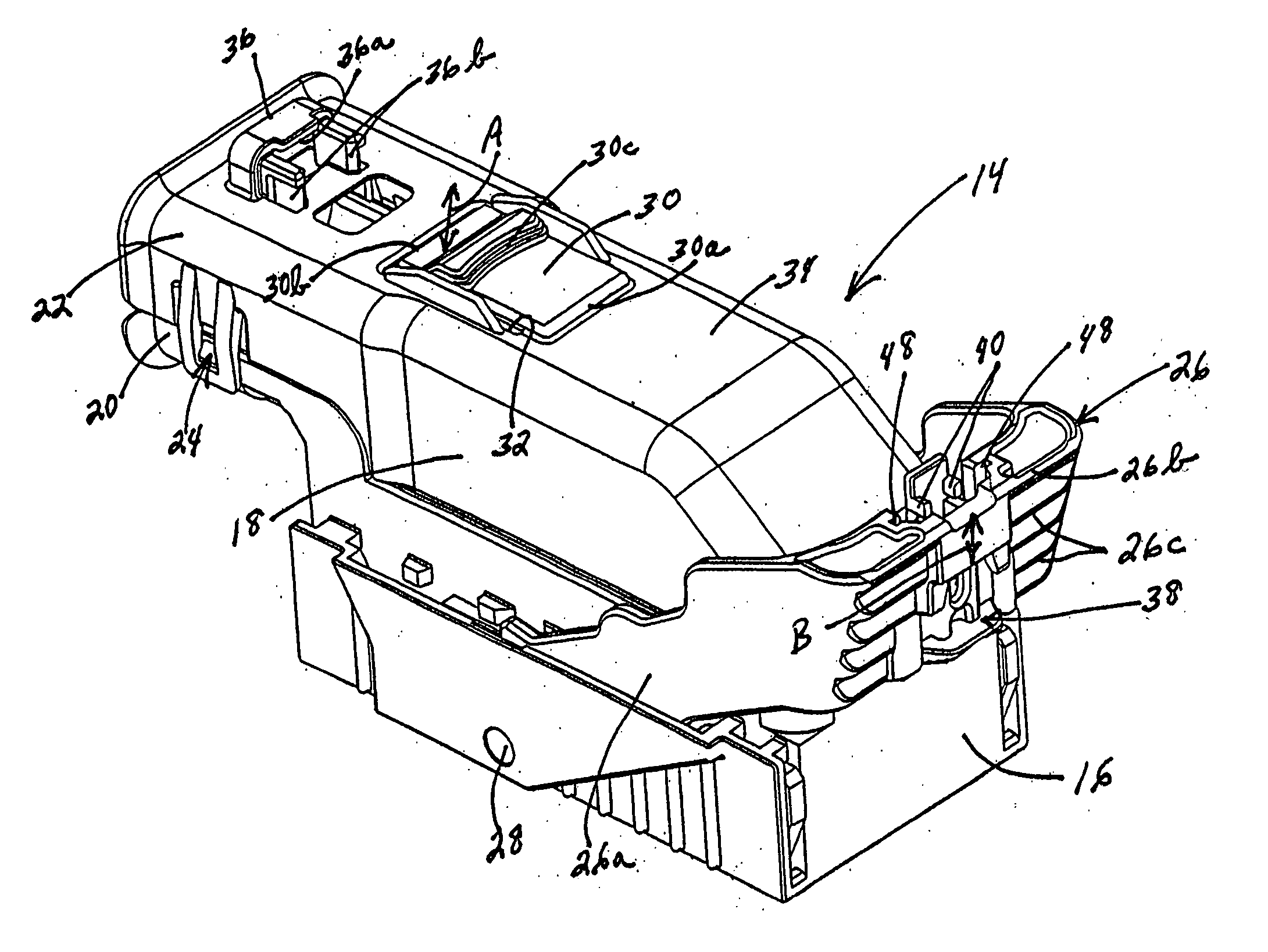
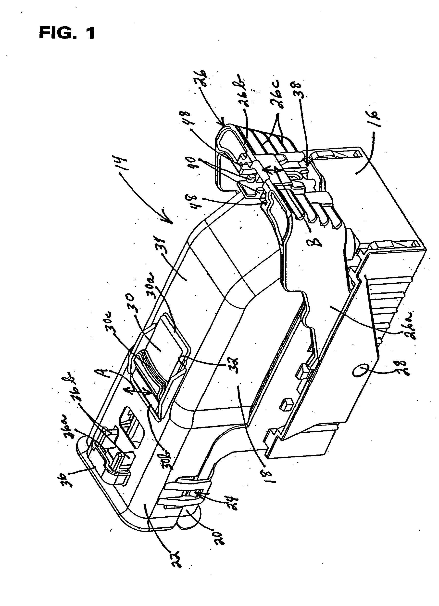
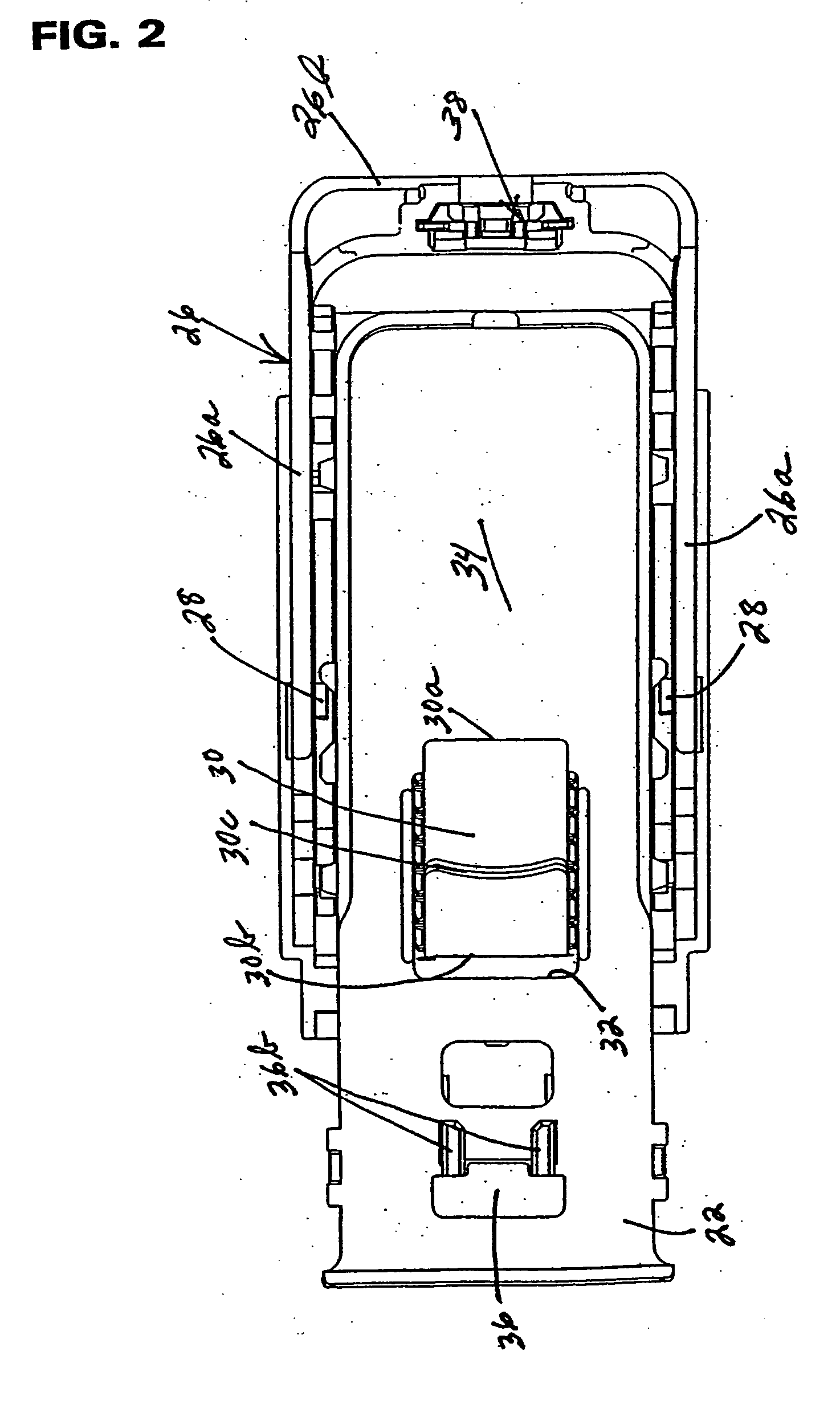
[0023] Referring to the drawings in greater detail, and first to FIGS. 1 and 2, the invention is embodied in a lever-type electrical connector, generally designated 14, which includes a connector body 16 and a wire shroud 18 secured to the top of the connector body. As is known in the art, connector body 16 mounts a plurality of conductive terminals (not visible in the drawings). The connector body is mateable with a second or complementary mating connector whereby the terminals of the mating connector interengage with the terminals of connector14. The connector body has a bracket portion 20 and the wire shroud has a bracket portion 22 which combine to define a mouth through which a plurality of electrical wires (not shown) extend for electrical connection to the terminals within connector body 16, as is known in the art. The bracket portions are latched together by an interengaging latching structure, generally designated 24.

[0024] Connector 14 is a lever-type connector which incl...


PUM


Abstract

An electrical connector includes a connector body and a wire shroud secured to the connector body. A mating assist lever is pivotally mounted on the body to be pivotable between an inoperative position and a latched position. A connector position assurance (CPA) member is slidably mounted on the mating assist lever to be slidable between an inoperative position and a locked position. Complementary interengaging locks are provided between the CPA member and the wire shroud to lock the mating assist lever in its latched position when the CPA member is moved to its locked position.

Description

FIELD OF THE INVENTION [0001] This invention generally relates to the art of electrical connectors and, particularly, to a lever-type electrical connector having a connector position assurance (CPA) member slidably mounted directly on the lever of the connector. BACKGROUND OF THE INVENTION [0002] With some electrical connectors, large forces are required to mate and unmate a connector with an associated connector because the connectors have a large number of terminals. Consequently, low-insertion-force connectors have been developed which enable mating and unmating with small forces by means of an operating lever. A typical lever-type electrical connector includes a first connector which has an actuating lever rotatably or pivotally mounted thereon for connecting and disconnecting the connector with a complementary mating second connector. The actuating lever and the second connector typically operate through some form of cam groove / cam follower arrangement for drawing the second co...

Claims


Application Information

Patent Timeline
IPC IPC(8): H01R13/62H01R13/58H01R13/629H01R13/639
CPCH01R13/5812H01R13/6295H01R13/62955H01R13/639
Inventor FLOWERS, ROBERT J.KOEHLER, KEITH G.
Owner MOLEX INC
Features
  • Generate Ideas
  • Intellectual Property
  • Life Sciences
  • Materials
  • Tech Scout
  • Unparalleled Data Quality
  • Higher Quality Content
  • 60% Fewer Hallucinations
Learn More