Light guide plate, surface light source device and display

a surface light source and light guide technology, applied in the field of light, can solve the problems of hardly changing the direction of light propagating almost along the emission face, unable to provide a highly effective emission, and unable to achieve the effect of highly effective emission and superior direction-conversion function

Inactive Publication Date: 2006-05-04
ENPLAS CORP
View PDF1 Cites 4 Cited by
  • Summary
  • Abstract
  • Description
  • Claims
  • Application Information

AI Technical Summary

Benefits of technology

[0045] The present invention solves problems which are involved in the technique of the above proposition. An object of the present invention is to provide a light guide plate which is improved not only as to have a superior direction-conversion function for light introduced sideways but also as to have an emission face on which finely irregular brightness hardly appears.
[0046] Another object of the present invention is to provide a surface light source device which effectively gives a high-quality illumination output almost free from finely irregular brightness by means of the improved light guide plate.
[0047] Still another object of the present invention is to provide a liquid crystal display which shows a high-quality display function by applying the improved surface light source device for illumination a liquid crystal display panel.
[0053] This controls the proportion of direct escaping light to the inner output which is inner-incident to the emission face. Further, the emission face may be provided with a great number of projection rows running approximately at right angles with respect to the incidence end face. This, if employed, further controls the proportion of direct escaping light to the inner output which is inner-incident to the emission face.
[0061] Further, the emission face of the light guide plate may be provided with a great number of projection rows running approximately at right angles with respect to the incidence end face. This, if employed, further controls the proportion of direct escaping light to the inner output which is inner-incident to the emission face.
[0063] Further to this, since a process of direction-conversion includes two steps, “producing of oblique incidence inner output light by means of micro-reflectors” and “producing of frontal output light by means of a direction modifying member”, the process is effected less forcibly in comparison with that effected by only a direction modifying member or only micro-reflectors, allowing an increased degree of flexibility in design.

Problems solved by technology

As known well, a simply transparent light guide plate without any modification is capable of deflecting light a little, providing a unsatisfactory brightness.
However, the light propagating almost along the emission face is hardly direction-modified.
Ways based on (2) or (3) scarcely provide a highly effective emission.
In particular, it is not advantageous that they fail to generate light rays which travel from the back face to the emission face.
However, prior arts as shown in FIG. 1a to FIG. 1c are subject to the following problems.
However, the above-proposed technique remains a problem unsolved.
As a result, a fine unevenness in brightness appears on the emission face.
However, arraying density is subject to a practical limit.

Method used


Image

  • Light guide plate, surface light source device and display
  • Light guide plate, surface light source device and display
  • Light guide plate, surface light source device and display

Examples


Embodiment Construction

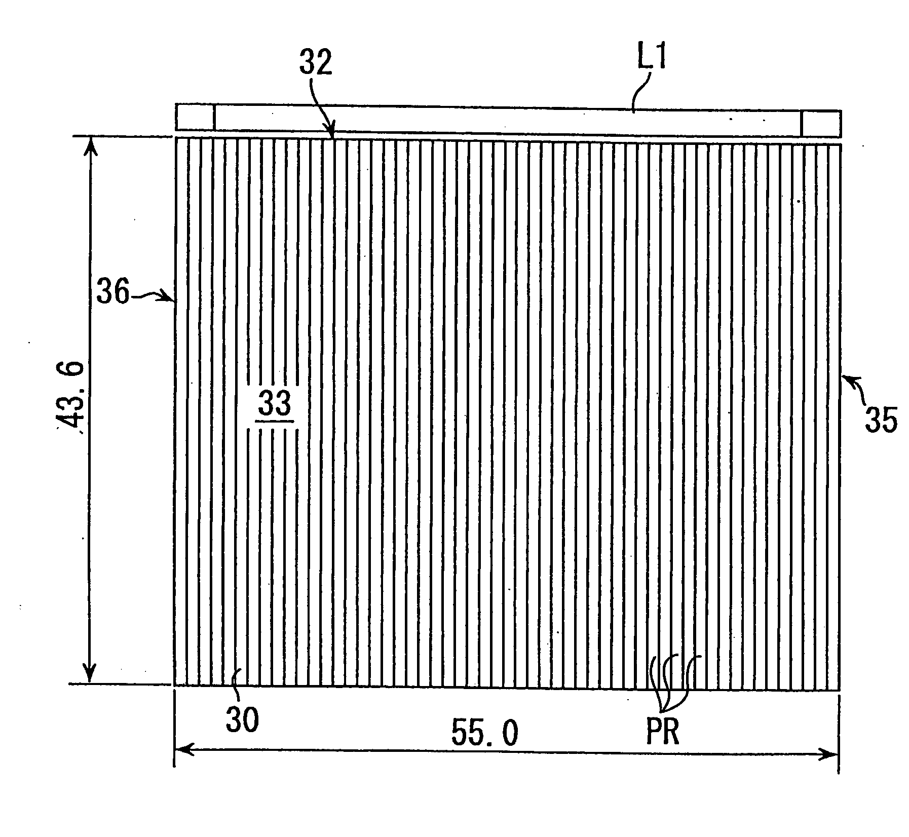
[0087] An outlined arrangement of an embodiment in accordance with the present invention is illustrated in FIGS. 4a and 4b. FIG. 4a is a top plan view and FIG. 4b is a side view from the left hand in FIG. 4a. FIG. 5 is an enlarged perspective view illustrating a micro-reflector employed in the same embodiment and around it, wherein a typical light path is depicted together.

[0088] In FIG. 4a, a prism sheet (direction modifying member) and a LCD panel are not shown. In FIG. 5, the LCD panel is not shown and only a partial illustration of some projection rows of a prismatic surface of the prism sheet is shown in order to give an easy illustration.

[0089] Numerals for size indication in mm are merely exemplary ones. It is noted that sizes of micro-reflectors and projection rows are exaggerated as required for giving easy illustrations in figures referred hereafter. A LCD panel PL is a typical example of object to be illuminated, which may be replaced by another object to be illuminated...


PUM

PropertyMeasurementUnit
θaaaaaaaaaa
orientationaaaaaaaaaa

Abstract

A guide plate 30 has a back face 34 provided with a great number of micro-reflectors 90 which has a guide portion and a conversion output portion including a valley. The conversion output portion reflects twice input light P at inner slopes, generating inner output light Q directed obliquely as to be distant from an incidence end face 32. Inner output light Q is inner-incident to a slope of projection row PR on an emission face 33, with the result that some of the inner-incident light becomes a direct escaping light and much of the other reaches the emission face 33 again after travelling along various paths. At the second time or later chances of escaping, an actual escaping occurs to generate an indirect escaping light. A mixed emission suitably blended of the direct and indirect light is directed to directions, which are modified to directions around a roughly frontal direction by prism sheet PS before being supplied to a LCD panel or the like to be illuminated. Blending of direct / indirect escaping light prevents fine brightness unevenness from appearing. Reflector RF, if arranged, brings an increased indirect escaping light. An emission has travelling directions inclinations of which are controlled while fine brightness unevenness are reduced.

Description

CROSS REFERENCE TO RELATED APPLICATIONS [0001] This application is based on and hereby claims priority to U.S. application Ser. No. 09 / 893,444 filed on Jun. 29, 2001, the contents of which are hereby incorporated by reference.BACKGROUND OF THE INVENTION [0002] 1. Field of the Invention [0003] The present invention relates to a light guide plate which is supplied with light sideways and direction-converts the supplied light inside to output an oblique emission, to a surface light source device employing the light guide plate and a direction modifying element in combination and to a liquid crystal display employing the surface light source device for illumination a liquid crystal display panel. [0004] 2. Description of the Related Art [0005] A well-known technique employs a light guide plate having an incidence end face provided by a side end face and an emission face provided by one of two major faces (i.e. faces larger than end faces), wherein light is introduced into the light guid...

Claims


Application Information

Patent Timeline
Patent Type & Authority Applications(United States)
IPC IPC(8): G02F1/1335H01L33/00G02B6/00F21S2/00F21V7/00F21V8/00F21Y103/00G02F1/13357
CPCG02B6/0036G02B6/0038G02B6/0053G02B6/0061G02F1/1335
Inventor OHKAWA, SHINGO
Owner ENPLAS CORP
Why Eureka
Try Eureka