Light guide plate, surface light source device and liquid crystal display

a surface light source and light guide plate technology, applied in waveguides, lighting and heating apparatuses, instruments, etc., can solve the problems of unsatisfactory brightness, and low light diffusion efficiency, and achieve the effect of hardly providing a highly effective emission

Inactive Publication Date: 2002-11-26
ENPLAS CORP
View PDF5 Cites 80 Cited by
  • Summary
  • Abstract
  • Description
  • Claims
  • Application Information

AI Technical Summary

Benefits of technology

The present invention aims to overcome the above-mentioned problem of the proposed technique. Accordingly, an object of the present invention is to provide a light guide plate which is improved not only as to have a superior direction-conversion function for light introduced sideways but also as to hardly show a fine unevenness in brightness on an emission face.
Another object of the present invention is to provide a surface light source device which is improved as to produce an output illumination not only with a high efficiency but also with a high-quality involving little fine unevenness in brightness by means of the improved light guide plate. Still another object of the present invention is to provide a liquid crystal display which gives a high-quality display screen by applying the improved surface light source device to an arrangement for lighting a LCD panel.
The present invention is according to a basic idea (as proposed in the above patent application) that inner reflections caused twice at inner surfaces of a micro-reflector is a direction-conversion process, and, further to the basic idea, the present invention employs a great number of projection rows formed on an emission face as to cause the emission to have diversified traveling histories, thereby solving the problem.
In the first place, the present invention improves a light guide plate comprising two major faces to provide an emission face and a back face, and an incidence end face for introducing light.
It is preferable to dispose a reflection member along the back face of the light guide plate in order to increase the indirectly escaping light. The reflection member reflects and returns the light, which has been inner-reflected at the projection rows and leaked through the back face, to the light guide plate, thereby giving the light chances of indirect escaping.
The surface light source device improved as above may be adopted as a surface light source device for a backlighting-type LCD having a LCD panel illuminated from the back side or for a frontlighting-type LCD having a LCD panel illuminated from the front side (i.e. from the viewer's side). In these cases, the performance of the surface light source device is reflected on that of the LCD. Thus, the LCD in accordance with the present invention has a display screen which looks well luminous.

Problems solved by technology

As known well, a simply transparent light guide plate without any modification is capable of deflecting light little, providing unsatisfactory brightness.
However, light diffusion involves a loss of light because of divergence toward useless directions.
Ways based on (2) or (3) hardly provide a highly effective emission.
In particular, it is not advantageous that they fail to generate light rays which travel from the back face to the emission face.
1. Light is hard to reach a region behind the slope 5b as viewed from the incidence face 2. Therefore, a reduction of formation pitch d hardly rises direction conversion efficiency and the emission face 3 is apt to show an unevenness in brightness.
2. Sufficient direction control in a plane parallel to the incidence face 2 is not effected. For instance, if beams G1 and G2 are parallel to the emission face 3 but not perpendicular to the incidence face 2, emission beams G1' and G2' will be diverged to the right or left as viewed from the incidence face 2. Actually, there is considerable light components which propagate not perpendicularly with respect to the incidence face 2 within the light guide plate 1. Accordingly, it is difficult to provide an emission to a desirable angle or within a desirable angle range spatially (i.e. in both planes parallel and vertical to the incidence face 2).
3. Light leaking through the back face 4 occurs easily because direction conversion for generating light directed to the emission face 3 relies upon once-occurring-reflection (at slope 5a). That is, the condition for total reflection is broken with ease at the reflection for direction conversion. For instance, if beams G1' and G2' are required to be directed to approximately frontal directions, inner-incidence angle .theta. is set at about 45 degrees. This is roughly the same as the critical angle for an interface between air and acrylic resin which is a typical material. Therefore, a considerable part of light propagating slightly downward leaks through the slope 5a.
However, the above-proposed technique remains a problem unsolved.
As a result, a fine unevenness in brightness appears on the emission face.
However, arraying density is subject to a practical limit.

Method used


Image

  • Light guide plate, surface light source device and liquid crystal display
  • Light guide plate, surface light source device and liquid crystal display
  • Light guide plate, surface light source device and liquid crystal display

Examples


Embodiment Construction

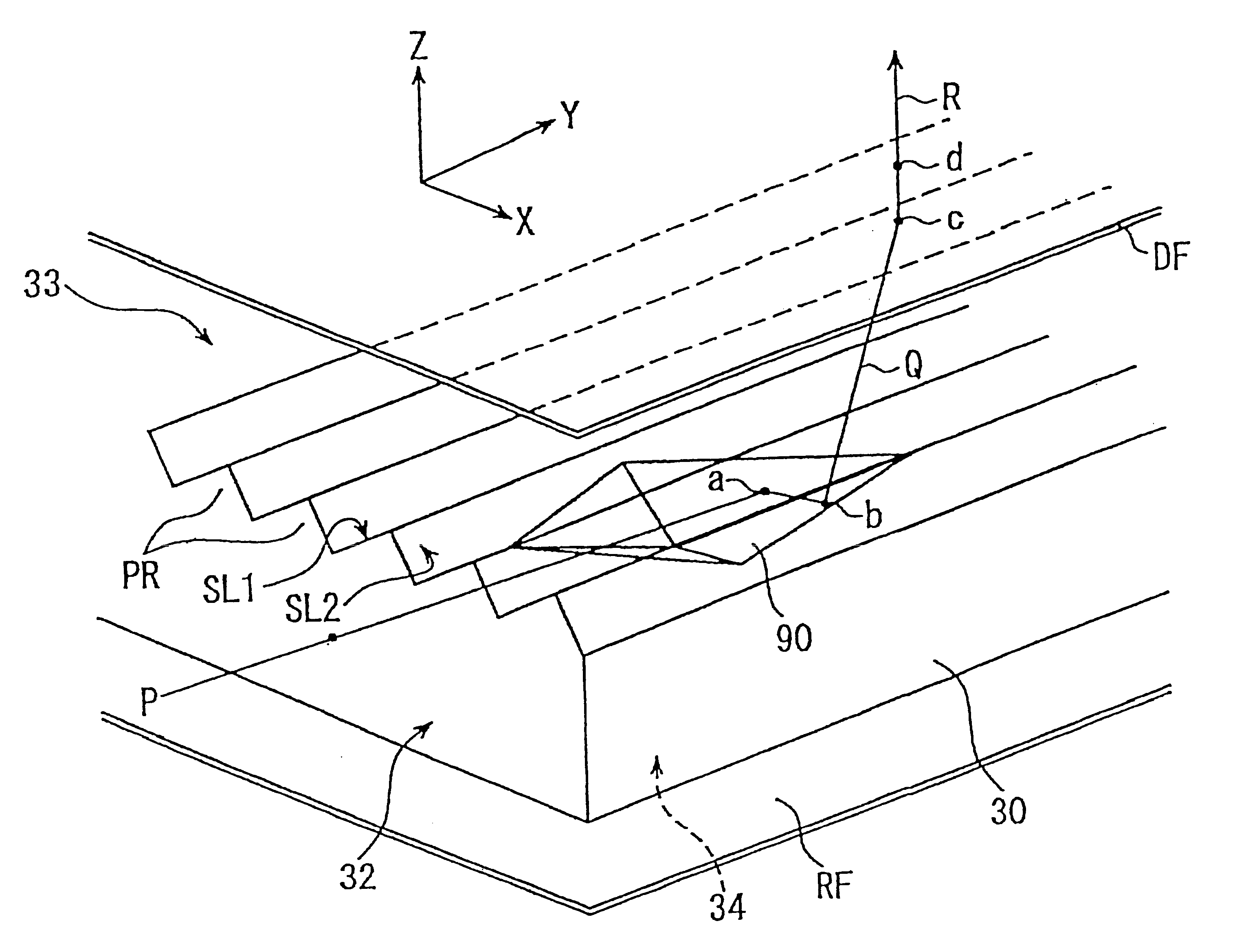
FIGS. 4a and 4b illustrate an outlined arrangement of an embodiment in accordance with the present invention. FIG. 4a is a plan view and FIG. 4b is a side view as viewed from the right hand in FIG. 4a. FIG. 5 is an enlarged perspective view of a micro-reflector and its surroundings in the embodiment, wherein typical light paths are shown.

In FIG. 4a, a diffusing plate and LCD panel is omitted in the illustration. In FIG. 5, the LCD panel is omitted in the illustration. Size values in mm are merely examples.

It is noted that illustration sizes of micro-reflectors or projection rows are exaggerated, as required, for the sake of easy understandings. LCD panel PL is merely a typical object to be illuminated, and accordingly, other objects to be illuminated may be arranged depending on uses.

In the first place, referring to FIGS. 4a and 4b, an incidence end face 32 is provided by a side end face of a light guide plate 30 made of a transparent material such as acrylic resin, cycloorefinic re...


PUM

PropertyMeasurementUnit
inner-incidence angleaaaaaaaaaa
critical angleaaaaaaaaaa
angleaaaaaaaaaa

Abstract

A surface light source device and LCD employs a light guide plate which is capable of a three-dimensional emission direction controlling and avoids fine unevenness in brightness from appearing. Light guide plate 34 has a back face 34 provided with a great number of micro-reflectors 90 each of which has a guiding portion and a conversion output portion including a valley getting narrower and shallower as being distant from the guiding portion. The conversion output portion reflects input light P twice at inner slopes to produce inner output light Q. Inner output light Q is inner-incident to a slope of projection raw PR. While some of the inner incident light becomes directly escaping light, some other of the inner incident light fails to escape directly, reaching emission face 33 after travelling further along various light paths. Indirectly escaping light is emitted at second or later chances of emission. Directly escaping light and indirectly escaping light overlap, thereby preventing fine unevenness in brightness from appearing. It is advantageous to dispose reflector RF for increasing indirectly escaping light.

Description

1. Field of InventionThe present invention relates to a light guide plate which is supplied with light sideways and deflects the light to output from an emission face, further relating to a surface light source device employing the light guide plate as well as to a liquid crystal display employing the surface light source device for back-lighting or front-lighting.2. Related ArtA surface light source device of a type comprises a light guide plate having an end face, through which light is introduced, and two major faces (i.e. faces larger than end faces) one of which provides an emission face, being employed for various uses such as back-lighting or front-lighting for a liquid crystal display. Basic performance of surface light source devices of such type greatly depends on light guide plates employed therein.A basic function of a light guide plate is to change a propagation direction (roughly in parallel with an emission face of the light guide plate) of light introduced into the l...

Claims


Application Information

Patent Timeline
Patent Type & Authority Patents(United States)
IPC IPC(8): F21V8/00F21Y103/02G02B6/00G02F1/1335G02F1/13357
CPCG02B6/0036G02B6/0038G02B6/0061Y10S385/901G02F1/1335
Inventor OHKAWA, SHINGO
Owner ENPLAS CORP
Why Eureka
Try Eureka