Check patentability & draft patents in minutes with Patsnap Eureka AI!

Wooden debris compressor

a wooden debris and compressor technology, applied in the field of wooden debris compressors, can solve the problems of inability to break bridging, wood debris may not easily fall into the feeding device, and affect the air quality and human health, and achieve the effect of continuous and smooth compression

Inactive Publication Date: 2006-05-11
SAN FORD MACHINERY
View PDF3 Cites 6 Cited by
  • Summary
  • Abstract
  • Description
  • Claims
  • Application Information

AI Technical Summary

Benefits of technology

[0007] This invention has been devised to offer a wooden debris compressor, which is provided with a plural poking rods in a poking device under a storing tank, for controlling falling volume of wooden debris by back-and-forth rotation of the poking rods, and also for breaking bridging conditions of wooden debris by ax-shaped knives at the end of the poking rods so as to let wooden debris smoothly fall down through the feeding hole. Further, a cutting device with a cutter is provided on a material room of the feeding device so the bridging conditions of wooden debris formed in the upper portion of the material room can be also broken by the cutter to fall easily down to the bottom. Thus, the wooden debris compressor in the invention breaks in due time bridging conditions possible formed under the storing tank and on the feeding device to continuously and smoothly compress wooden debris, effectively getting rid of the drawbacks of the conventional wooden debris compressor, that is, interruption of compressing operation and idle running of the power under no load.

Problems solved by technology

Common wooden machines produce lots of wooden debris in their operation, and light and fluffy wooden debris may easily fly around in the air, giving bad effect to the air quality and human health.
In disposing it in a bag or container, it needs much space, and moreover, it is also very flammable, having potential danger of get burned to cause disaster to lives and real estates.
However, common wooden debris is not in power condition to cause bridged conditions in case it is deposited and accumulated in a vertical condition so wooden debris may not easily fall into the feeding device in the conventional wooden debris compressor just described above.
But the poking device has an elongate poking rod with only a little dimension for poking, incapable to break bridging condition completely and leaving some unbroken portion of the bridging conditions of wooden debris.
Therefore, wooden debris cannot smoothly be fed into the feeding device, interrupting the operation of the conventional wooden debris compressor.
In addition, during the process of wooden debris falling from the bottom of the storing tank to the feeding rod, bridging conditions may also happen so enough wooden debris may not move into the compressing device, causing interruption of compressing operation.
Besides, the compressing device may also operate even in case of no load, resulting in waste of time and troubles in operational process.

Method used


Image

  • Wooden debris compressor
  • Wooden debris compressor
  • Wooden debris compressor

Examples


Embodiment Construction

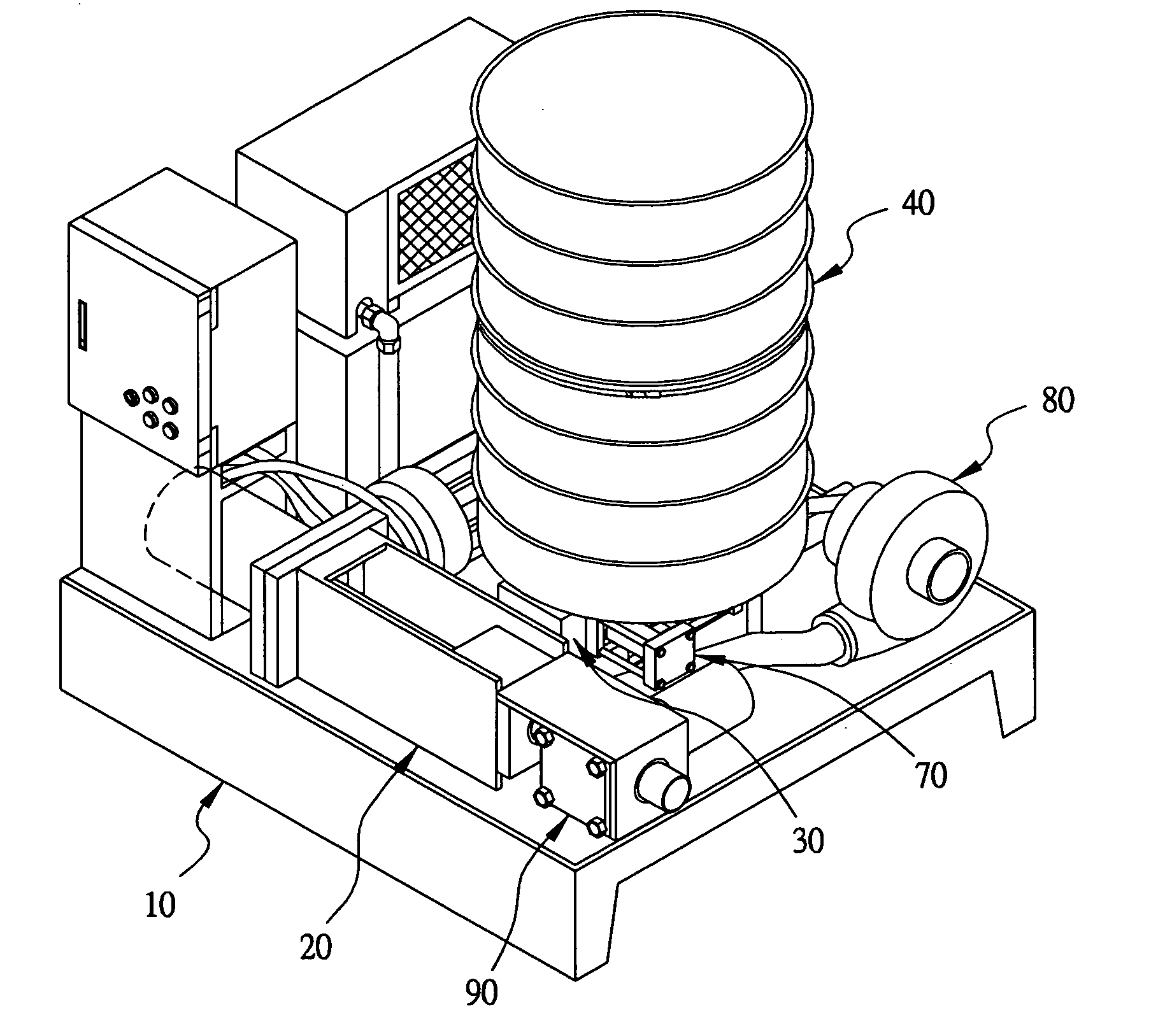
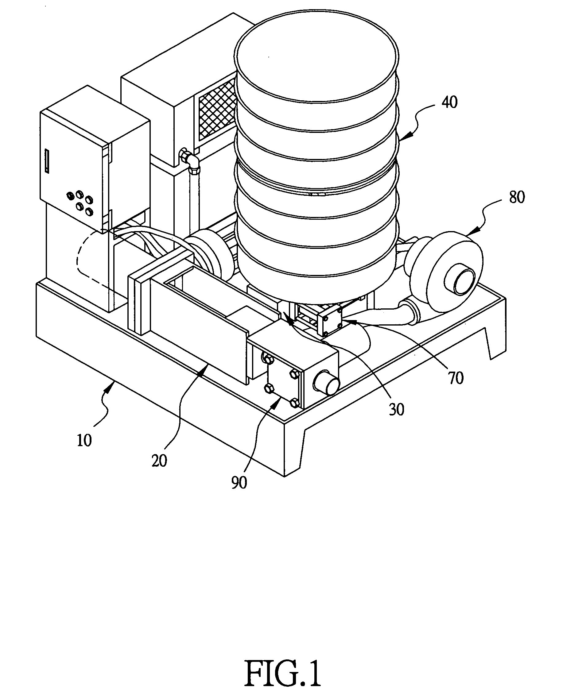
[0017] A preferred embodiment of a wooden debris compressor in the present invention, as shown in FIGS. 1, 2 and 3, includes a base 10, a compressing device 20, a feeding device 30, a storing tank 40, a poking device 50, a reciprocating device 60, a cutting device 70, a cooling device 80, and a clamping device 90 as main components.

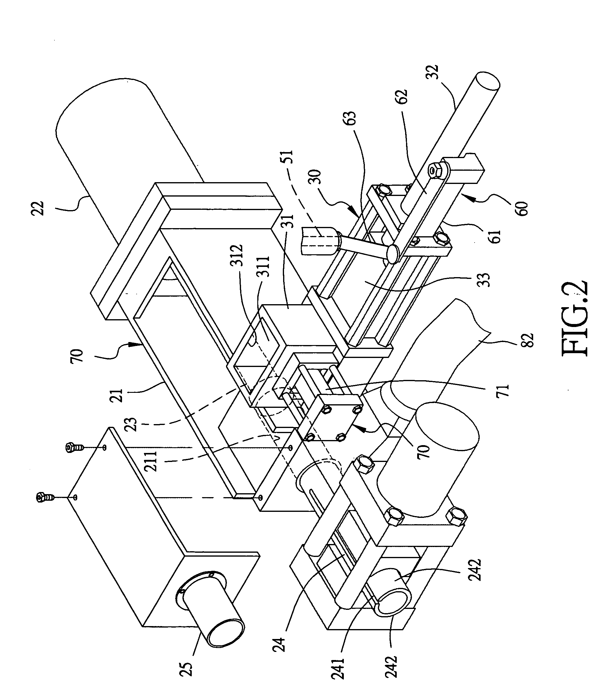
[0018] The compressing device 20 consists of a base member 21, a compress room 211 formed on the base member 21, a liquid cylinder 22 with a compress rod 23 that extends and reciprocates in the compress room 211 for compressing wooden debris into blocks, and a pressure tube 24 fixed at the other end of he liquid tank 22 and communicating with the compress room 211. The pressure tube 24 has two opposite lengthwise slots 241 to divide it into two half tubes 242 that can expand to some extent in case of pressure caused by wooden debris compressed therein. Further, a debris block outgoing tube 25 is fixed with an outer end of the pressure tube 24, for finish...


PUM


Abstract

A wooden debris compressor includes a storing tank, and a poking device under the storing tank provided with plural poking rods fixed spaced apart in a definite angle. Then alternate back-and-forth rotation of the poking rods controls the volume of wooden debris falling down, and at the same time ax-shaped knives at outer ends of the poking rods rotates also back and forth alternately to break bridged conditions of wooden debris to let wooden debris smoothly fall down through a feeding hole. Then a cutting device with a cutter is provided on a material room of a feeding device to cut wooden debris in bridged conditions in an upper portion of the material room to let it fall down in a lower portion. Then the compressor can carry out compressing operation continuously and smoothly.

Description

BACKGROUND OF THE INVENTION [0001] 1. Field of the Invention [0002] This invention relates to a wooden debris compressor, particularly to one compressing wooden debris into wooden debris blocks for use. [0003] 2. Description of the Prior Art [0004] Common wooden machines produce lots of wooden debris in their operation, and light and fluffy wooden debris may easily fly around in the air, giving bad effect to the air quality and human health. In disposing it in a bag or container, it needs much space, and moreover, it is also very flammable, having potential danger of get burned to cause disaster to lives and real estates. [0005] A conventional wooden debris compressor has been developed, storing wooden debris in a storing tank with a poking device provided therein, for poking wooden debris to fall into a compressing device. Then a pressing rod in the compressing device compresses wooden debris into debris blocks. [0006] However, common wooden debris is not in power condition to caus...

Claims


Application Information

Patent Timeline
Patent Type & Authority Applications(United States)
IPC IPC(8): B30B15/30
CPCB27N3/20B30B11/225B30B11/265B30B15/302Y10S100/906
Inventor CHENG, CHIEH-YUAN
Owner SAN FORD MACHINERY
Features
  • R&D
  • Intellectual Property
  • Life Sciences
  • Materials
  • Tech Scout
  • Unparalleled Data Quality
  • Higher Quality Content
  • 60% Fewer Hallucinations
Learn More